Lecteur RFID RC522

published: 3 November 2019 / updated 3 November 2019

Lire cette page en français


module RFID RC522

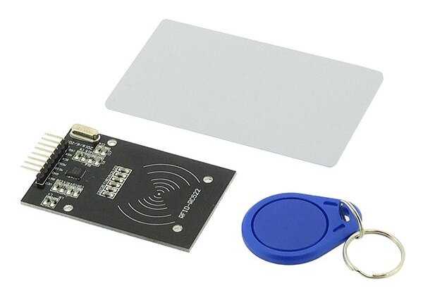
Attention ce module fonctionne sous 3,3 Volt !!!

Branchement

Pour le branchement cela va dépendre de la carte arduino utilisé (utilisation du SPI), ci dessous le tableau récapitulatif.

Signal  MFRC522
Reader/PCD
Arduino
Uno/101
Arduino
Mega
Arduino
Nano v3
Arduino
Leonardo/Micro
Arduino
Pro Micro
VCC1 ------> 3,3 V <------
RST/Reset2 RST 9 5 D9 RESET/ICSP-5 RST
GND3 ------> GND <------
IRQ4
SPI MISO5 MISO 12 / ICSP-1 50 D12 ICSP-1 14
SPI MOSI6 MOSI 11 / ICSP-4 51 D11 ICSP-4 16
SPI SCK7 SCK 13 / ICSP-3 52 D13 ICSP-3 15
SPI SS8 SDA(SS) 10 53 D10 10 10
Connecteurs RC522
// source: PDF MFRC522.pdf Serial Peripheral Interface A serial peripheral interface (SPI compatible) is supported to enable high-speed communication to the host. The interface can handle data speeds up to 10 Mbit/s. When communicating with a host, the MFRC522 acts as a slave, receiving data from the external host for register settings, sending and receiving data relevant for RF interface communication. An interface compatible with SPI enables high-speed serial communication between the MFRC522 and a microcontroller. The implemented interface is in accordance with the SPI standard. The timing specification is given in Section 14.1 on page 78. The MFRC522 acts as a slave during SPI communication. The SPI clock signal SCK must be generated by the master. Data communication from the master to the slave uses the MOSI line. The MISO line is used to send data from the MFRC522 to the master. Data bytes on both MOSI and MISO lines are sent with the MSB first. Data on both MOSI and MISO lines must be stable on the rising edge of the clock and can be changed on the falling edge. Data is provided by the MFRC522 on the falling clock edge and is stable during the rising clock edge. SPI read data Reading data using SPI requires the byte order shown in Table 6 to be used. Table 6. MOSI and MISO byte order Line Byte 0 Byte 1 Byte 2 To Byte n Byte n + 1 MOSI address 0 address 1 address 2 ... address n 00 MISO X[1] data 0 data 1 ... data n  1 data n It is possible to read out up to n-data bytes. The first byte sent defines both the mode and the address. [1] X = Do not care. Remark: The MSB must be sent first.