Serial to parallel converter 74HC595
published: 17 November 2019 / updated 16 November 2020
Presentation

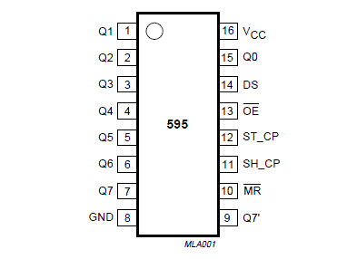
The symbols are from the Texas Instruments documentation.
| PIN | SYMBOL | DESCRIPTION |
|---|---|---|
| 1 | Q1 | parallel data output |
| 2 | Q2 | parallel data output |
| 3 | Q3 | parallel data output |
| 4 | Q4 | parallel data output |
| 5 | Q5 | parallel data output |
| 6 | Q6 | parallel data output |
| 7 | Q7 | parallel data output |
| 8 | GND | ground (0 V) |
| 9 | Q7 | parallel data output |
| 10 | SRCLR | master reset (active LOW) |
| 11 | SRCLK | Shift Register CLocK input |
| 12 | RCLK | Register CLocK input |
| 13 | OE | output enable (active LOW) |
| 14 | SER | SERial data input |
| 15 | Q0 | parallel data output |
| 16 | VCC | positive supply voltage |
Connecting the 74HC595 converter
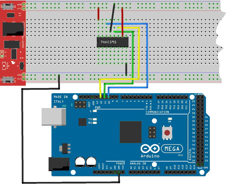
In order not to overload the ARDUINO board, the converter is powered by a source external, here in red on the prototyping board.

| pin | vers - to |
|---|---|
| 10 | SRCLR -> external +5V |
| 11 | SRCLK -> PB6 - pin 12 ARDUINO MEGA |
| 12 | RCLK -> PB5 - pin 11 ARDUINO MEGA |
| 13 | OE -> external GND |
| 14 | SER -> PB4 - pin 10 ARDUINO MEGA |
| 16 | VCC -> external +5V |
Serial to parallel conversion
We define in advance the PORTB:
\ for more 1 74HC595, change 1 by number of HC595
1 constant NB_74HC595
NB_74HC595 8 * constant NB_REG_PINS \ number of Register Pins

\ PORTB
37 constant PORTB	\ Port B Data Register
36 constant DDRB	\ Port B Data Direction Register
\ 35 constant PINB	\ Port B Input Pins - unused
The words defPIN: high low output input and pin@ are described
in the article Definition and management of PORT connections
With defPIN: we create the words SER RCLK SRCLK. These words
designates connectors of the ARDUINO cate and are named according to their use in relation
with the 74HC595 converter:
\ for Arduino MEGA
PORTB %00010000 defPIN: SER     \ PB4 -> pin 14 on the 74HC595 - dataPin
PORTB %00100000 defPIN: RCLK    \ PB5 -> pin 12 on the 74HC595 - latchPin
PORTB %01000000 defPIN: SRCLK   \ PB6 -> pin 11 on the 74HC595 - clockPin
\ PORTB %10000000 defPIN: OE      \ PB7 -> pin 13 on the 74HC595
The word init.74HC595 initializes the bits of the PORTB designated by
SER RCLK SRCLK as outputs and set these bits low.
: init.74HC595 ( ---)
    SER     output
    RCLK    output
    SRCLK   output
    SER     low
    RCLK    low
    SRCLK   low
  ;
The word csend sends a byte to the 74HC595 converter. The
word csend provides serialization of the bit byte:
: csend ( c ---)
    RCLK low                    \ latchPin LOW
    NB_REG_PINS
    for
        dup $80 and
        if      SER high        \ datapin HIGH
        else    SER low         \ datapin LOW
        then
        1 lshift
        SRCLK high              \ clockPin HIGH
        SRCLK low               \ clockPin LOW
    next
    drop
    RCLK high                   \ latchPin HIGH
  ;
Complete source code
The complete listing is available here: 8 bit data in serial and send it to 74HC595 chip
