Understanding ARDUINO card connectors
published: 4 November 2019 / updated 18 June 2020

Preamble
Unlike the C language for ARDUINO, the FORTH language does not have an IDE integrating the translation of the connector numbers to the pin numbers.
In C language:
void setup()
{
pinMode(4, OUTPUT);
pinMode(5, OUTPUT);
pinMode(6, OUTPUT);
pinMode(11, OUTPUT);
pinMode(13, OUTPUT);
pinMode(A2, OUTPUT);
pinMode(A3, OUTPUT);
pinMode(A4, OUTPUT);
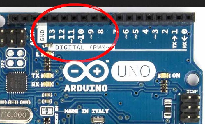
} The numbers of the pins correspond to the numbers inscribed on the card in front of each connector:
In C language, this translation is done through a complex C library. This library associates the connector number to its PORT register and the corresponding bit in this port.
These C language libraries simplify programming for beginners. In return, the code binary generated by the compiler C is cluttered with slags specific to these libraries.
FORTH language does not use any libraries outside of an initial dictionary. It will therefore be necessary define for each connector the PORT and the bit associated with a pin as defined in language C.
This definition is initially a constraint. But if we then master the analysis of card connectors ARDUNIO, it becomes very easy to create the words managing the PORTS and registers.
Analysis of ARDUINO board connectors
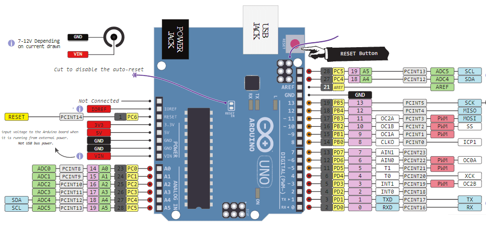
Here is the map of the connectors of an ARDUINO UNO board:
Isolate the part of the connectors managing the PORT B:
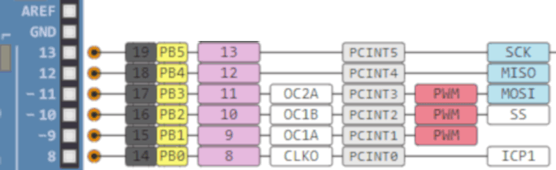
From left to right for the connector 8:
8 -> 14 -> PB0 -> 8 -> CLK0 -> PCINT0 -> ICP1
Detailed analysis of this line:
- 8: number of the connector inscribed on the ARDUINO board;
- 14: in black on dark gray - logical pin number;
- PB0: in black on yellow - port number and bit in this port;
- 8: in purple - repetition of the connector number on the card;
- CLK0: in black on white - function associated with a bus, here SPI;
- PCINT0: in black on light gray - hardware interrupt number, here interrupt 0;
- ICP1: in black on white - here Input Capture Pin
In all this information, the one that interests us in priority is the association between the physical connector (here 8) and the PORT, here PB0: Port B bit 0
FORTH translation of a physical connector
In FORTH, we define the ports as constants:
\ PORTB
37 constant PORTB	\ Port B Data Register
36 constant DDRB	\ Port B Data Direction Register
35 constant PINB	\ Port B Input Pins
These addresses for the PORTB are identical regardless of the ARDUINO cards.
On an ARDUINO board, a port is an 8-bit register accessible by its address, here 37 in decimal, $25 in hexadecimal:
37 constant PORTB \ Port B Data Register
is equivalent as:
$25 constant PORTB \ Port B Data Register
To isolate a bit in this register, here PORTB, it is necessary to use a binary mask:
- %00000001 for bit 0 - $01 in hexadecimal;
- %00000010 for bit 1 - $02 in hexadecimal;
- %00000100 for bit 2 - $04 in hexadecimal;
- %00001000 for bit 3 - $08 in hexadecimal;
- %00010000 for bit 4 - $10 in hexadecimal;
- %00100000 for bit 5 - $20 in hexadecimal;
- %01000000 for bit 6 - $40 in hexadecimal;
- %10000000 for bit 7 - $80 in hexadecimal;
So, a connector will always be accessible via a pair of values:
- the PORT via its 8-bit physical address;
- the masking bit written in an 8-bit value.
You can define a pin as follows, for example for connector 8:
: pin8 ( --- msk adr )
    %00000001 PORTB ;
To activate this connector, it will be necessary to declare in the DDRB register that this connector is activated at the output:
: init.out.pin8 ( ---)
    pin8 1- mset ;
Then to enable and disable this connector 8:
: pin8.on ( ---)
    pin8 mset ;
: pin8.off ( ---)
    pin8 mclr ;
Here we have done at the simplest, to illustrate the management of connector 8. We will see later how to factor the code.
Naming the connectors
Let's go back to our connector 8 which corresponds to the first bit in PORT B. What does it plug into?
An LED? A relay? A buzzer? So why name pin8?
If we develop an application on our ARDUINO card, it may happen that we are obliged
to move the LED, the relay, the buzzer to another connector. And so, it will be necessary to redefine
PIN8
: pin8 ( --- msk adr )
    %10000000 PORTF ;
Here, we moved the connector to the highest weight bit of PORT F
on an ARDUINO MICRO board (Connector 42). Without renaming pin8,
the program will work.
The logic would be to rename pin8 to pin42. But
if we have used pin8 later in our source code, we will need
rename all these occurrences of pin8.
The solution is to rename according to the use of the connector. We use the
connector 8 to light a red LED? So we define a word LED.red
like this:
: LED.red ( --- msk adr )
    %00000001 PORTB ;
: init.LED.red ( ---)
    LED.red 1- mset ;
: LED.red.on ( ---)
    LED.red mset ;
: LED.red.off ( ---)
    LED.red mclr ;
You understand immediately that moving the red LED on another connector, it
just change the definition of the word LED.red. All the others
definitions using LED.red will not need to be changed.
This is the naming scheme that is used in this article Revisited management of traffic lights
Extract:
: traffic.lights ( ---)
    LED.green   led.ON   3000 ms    LED.green   led.OFF
    LED.yellow  led.ON    800 ms    LED.yellow  led.OFF
    LED.red     led.ON   3000 ms    LED.red     led.OFF  ;
Without reading the beginning of the code, you immediately understand how
works the word traffic.lights!
Factoring the FORTH code
When programming in FORTH language, you should try to write definitions as well. simple and shorter as possible. If the same code is repeated in several definitions, it is necessary to group these portions of code into a new word and replace these portions of code by that word.
This technique is called code factorization. FORTH language is not a object-oriented language. It's even a language closer to the assembler than any other programming language. It's easy to make mistakes and difficult to find and delete them.
By creating words with simple definitions, the focus of these words becomes easy. Every word, once tested, must become a black box, a box tested and reliable. Only must be taken into account the nature of the input and output data for each word.
Let's go back to our LEDs on connectors 8 and following of PORT B. Connect four LEDs and a relay:
: LED1 ( --- msk adr )
    %00000001 PORTB ;
: LED2 ( --- msk adr )
    %00000010 PORTB ;
: LED3 ( --- msk adr )
    %00000100 PORTB ;
: LED4 ( --- msk adr )
    %00001000 PORTB ;
: RELAY ( --- msk adr )
    %00010000 PORTB ;
In the FORTH language, the word : is a word definition word, such as
variable or constant. Although being a close language
of the machine, the FORTH language has two words, CREATE DOES>
to create word definitions words.
: defPIN: ( PORTx mask ---| create c, c, \ compile PORT and pin mask does> dup c@ \ push pin mask swap 1+ c@ \ push PORT ;--- mask port)
We just defined the word defPIN: which is a word to define
the connectors:
eeprom
%00000001 PORTB defPIN: LED1
%00000010 PORTB defPIN: LED2
%00000100 PORTB defPIN: LED3
%00001000 PORTB defPIN: LED4
%00010000 PORTB defPIN: LED5
In the word defPIN:, the code part create , ,
recovers stacked data when defPIN: is executed.
In the word defPIN:, the code part does> dup @ swap 2+ @
retrieves the memory address to which the previously compiled parameters are stored
and stack this data. If we run LED1, we will stack the values 1 and PORTB.
FORTH language is extensible. When you develop a program, there is no one side the language and on the other your program.
An application in FORTH language extends the FORTH language. Your application integrates language FORTH just like all the pre-defined words of the FORTH language.
The vast majority of versions of the FORTH language are written at 20% in assembler and at 80% in FORTH language!
FORTH contains all the tools to create a meta-language!
Previously, we had defined:
: LED.red ( --- msk adr )
    %00000001 PORTB ;
: init.LED.red ( ---)
    LED.red 1- mset ;
: LED.red.on ( ---)
    LED.red mset ;
: LED.red.off ( ---)
    LED.red mclr ;
Here is the factored code:
\ Set DDRx so its corresponding pin is output.
: output ( pinmask portadr -- )
    1- high
  ;
\ Set DDRx so its corresponding pin is input.
: input  ( pinmask portadr -- )
    1- low
  ;
\ Turn a pin on, dont change others
: high ( pinmask portadr -- )
    mset
  ;
\ Turn a pin off, dont change others
: low ( pinmask portadr -- )
    mclr
  ;
Utilisation:
LED.red output
LED.red high
Turn on the red LED ...
PORT B on ARDUINO cards
On an ARDUINO UNO board, only bits 0 to 5 of PORT B are physically accessible on the map ARDUINO. On the ARDUINO MEGA board all the bits of PORT B are accessible.
In this table, you will find the correspondence of the bits of PORT B and the physical connectors Related:
| ARDUINO | B7 | B6 | B5 | B4 | B3 | B2 | B1 | B0 |
|---|---|---|---|---|---|---|---|---|
| UNO | 13 | 12 | 11 | 10 | 9 | 8 | ||
| MEGA | 13 | 12 | 11 | 10 | 50 | 51 | 52 | 53 |
| MICRO | 12 | 30 | 29 | 28 | 11 | 10 | 9 | 8 |
| NANO | 17 | 16 | 15 | 14 | 13 | 12 |
If you have to change an ARDUINO card by another one of a model, it will take take into account these disparities to adapt your code in FORTH language.
If you correctly factor your code in FORTH language, it will be easy to isolate the initialization part specific to your ARDUINO card type.
Caution: do not confuse physical connector numbers and pin numbers
On the ARDUINO cards, the physical connectors are marked, some by numbers, others by their function, example: GND, TX, RX, 5V, etc ...
The mapping for associating pin numbers with physical connectors is in this document:
Pin out map on ARDUINO DUE
Pin out map on ARDUINO MEGA 2560
Pin out map on ARDUINO MICRO
Pin out map on ARDUINO NANO
Pin out map on ARDUINO UNO
Pin out map on ARDUINO YUN
For example, the led '13' which is connected to the ARDUINO MEGA board with the physical terminal 13 is related to the PIN 26. In all our texts, the term "pin" will always refer to PIN code XX as referenced in the technical documents of ARDUINO cards. The mention of a physical connector will be done with the term 'terminal'. Example:
PIN 19 (terminal 53) (penultimate terminal, all at the bottom, left on an ARDUINO MEGA 2560 board)
To learn more about how to program the connectors of the different ARDUINO boards:
Understanding ARDUINO card connectors