The SPI interface of ARDUINO boards
published: 9 July 2026 / updated 9 July 2026

article: 04 nov. 2019 / mis à jour 24 nov. 2019
The code parts are in FORTH language, FlashForth version.
The complete list of management of the SPI interface is available here:
Words to drive the SPI module on the ATmega2560
Presentation
Serial Peripheral Interface (SPI) is a synchronous serial data protocol used by microcontrollers for communicating with one or more peripheral devices quickly over short distances. It can also be used for communication between two microcontrollers.
With an SPI connection there is always one master device (usually a microcontroller) which controls the peripheral devices. Typically there are three lines common to all the devices:
- MISO (Master In Slave Out) - The Slave line for sending data to the master,
- MOSI (Master Out Slave In) - The Master line for sending data to the peripherals,
- SCK (Serial Clock) - The clock pulses which synchronize data transmission generated by the master and one line specific for every device,
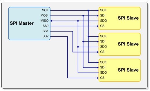
- SS (Slave Select) - the pin on each device that the master can use to enable and disable specific devices.
SPI connections on the Arduino board
On the Arduino UNO board, Duemilanove and other cards based on the ATmega 168/328, the SPI bus uses the pins:
- 10 : SS
- 11 : MOSI
- 12 : MISO
- 13 : SCLK
On the Arduino Mega, these are the pins:
- 50 : MISO
- 51 : MOSI
- 52 : SCLK
- 53 : SS
Definition of ports and registers
For all ARDUINO cards, we first define the ports and registers used through the SPI interface:
\ Registers of interest
$24 constant DDRB       \ Port B Data Direction Register
$25 constant PORTB      \ Port B Data Register

$4c constant SPCR       \ SPI Control Register
$4d constant SPSR       \ SPI Status Register
$4e constant SPDR       \ SPI Data Register
Then, the registers of the SPI interface are defined. List of registers for all cards ARDUINO, except MEGA cards:
\ bit masks for ATmega328
%000100 constant mSS1   ( PB2 )
%001000 constant mMOSI  ( PB3 )
%010000 constant mMISO  ( PB4 )
%100000 constant mSCK   ( PB5 )
List of registers for ARDUINO MEGA cards:
\ bit masks for ARDUINO MEGA
%00000001 constant mSS1   ( PB0 )
%00000010 constant mSCK   ( PB1 )
%00000100 constant mMOSI  ( PB2 )
%00001000 constant mMISO  ( PB3 )
$80 constant mSPIF      \ SPI Interrupt Flag
$40 constant mWCOL      \ Write Collision Flag
Selection of the slave
In the parameters above, the mSS1 constant points to the bit that
select slave 1 in the PORTB register.
If you need to manage multiple slaves, you will need to define as many constants that there are slaves.
: slave.select ( mSSx -- )     \ select slave x in mSSx constant
    dup DDRB  mset      \ SS as output
        PORTB mclr      \ deselect
  ;
: slave.deselect ( mSSx -- )   \ unselect slave
    dup DDRB  mset      \ SS as output
        PORTB mset      \ deselect
  ;
The SPCR register (SPI Control Register)
The SPI control register (SPCR) has 8 bits, each bit controlling a particular parameter of the SPI module:
| bit 7 | bit 6 | bit 5 | bit 4 | bit 3 | bit 2 | bit 1 | bit 0 |
|---|---|---|---|---|---|---|---|
| SPIE | SPE | DORD | MSTR | CPOL | CPHA | SPR1 | SPR0 |
SPIE (SPI Interrupt Enable) bit
Set SPIE to one if you want the SPI interrupt to be executed when a serial transfer is completed.
SPE (SPI Enable) bit
If you want to use the SPI, you must set this bit.
%01000000 constant SPCR_SPE     \ SPI Enable
: spi.enable ( ---)
    SPCR_SPE SPCR mset ;
: spi.disable ( ---)
    SPCR_SPE SPCR mclr ;
DORD (Data Order) bit
You can choose in which order the data will be transmitted. Set DORD to one to send the least significant bit (LSB) first. Set DORD to zero to send the most significant bit (MSB) first.
%00100000 constant SPCR_DORD \ Data Order
: LSB.first ( --- )     \ select LOW Signifiant Bit first
    SPCR_DORD SPCR mset ;
: MSB.first ( --- )     \ select MOST Signifiant Bit first
    SPCR_DORD SPCR mclr ;
MSTR (Master/Slave Select) bit
Set MSTR to configure the AVR as a Master SPI device. Clear MSTR to configure it as a Slave.
%00010000 constant SPCR_MSTR    \ Master/Slave Select
: Master.mode
    SPCR_MSTR SPCR mset ;
: Slave.mode
    SPCR_MSTR SPCR mclr ;
CPOL (Clock Polarity) and CPHA (Clock Phase) bits
As stated previously, Master and Slave must agree on how to interpret the clock signal. The first thing to do is to configure which logic level the clock will be in when the SPI is idle. If CPOL is set to one, SCK is high when idle, and if CPOL is set to zero, SCK is low when idle. The second thing is to configure during which clock transition the data will be sampled. Set CPHA to sample the data on the trailing (last) edge, and clear CPHA to sample the data in the leading (first) edge.
So, there are four different ways of configuring the clock generation, which are known as 'SPI modes'. The following table summarizes the four SPI modes:
| SPI mode |
CPOL | CPHA | sample |
|---|---|---|---|
| 0 | 0 | 0 | Leading (Rising) Edge |
| 1 | 0 | 1 | Trailing (Falling) Edge |
| 2 | 1 | 0 | Leading (Falling) Edge |
| 3 | 1 | 1 | Trailing (Rising) Edge |
\ SPI mode
%00000100 constant SPCR_CPHA    \ Clock Phase
%00001000 constant SPCR_CPOL    \ Clock Polarity
: Mode0
    SPCR_CPHA SPCR mclr   \ Idle CLK = 0
    SPCR_CPOL SPCR mclr  \ Sample on leading edge
  ;
: Mode1
    SPCR_CPHA SPCR mclr   \ Idle CLK = 0
    SPCR_CPOL SPCR mset    \ Sample on trailing edge
  ;
: Mode2
    SPCR_CPHA SPCR mset     \ Idle CLK = 1
    SPCR_CPOL SPCR mclr    \ Sample on trailing edge
  ;
: Mode3
    SPCR_CPHA SPCR mset     \ Idle CLK = 1
    SPCR_CPOL SPCR mset    \ Sample on leading edge
  ;
SPR1 and SPR2 (SPI Clock Rate Select) bits
The SPR bits configure the frequency of the clock signal. Since the Slave reads the clock from an input pin, the SPR bits have no effect on the Slave. The frequency of the SPI clock is related to the frequency of the AVR oscillator. The faster the SPI clock signal is, the faster the data trasfer will be, however, you must respect the maximum clock frequency specified by the Slave. The following table summarizes the relationship between the SCK frequency and the SPR bits:
| SPR1 | SPR0 | SCK frequency |
|---|---|---|
| 0 | 0 | fosc/4 |
| 0 | 1 | fosc/16 |
| 1 | 0 | fosc/64 |
| 1 | 1 | fosc/128 |
\ SPI clock speed
%00000010 constant SPCR_SPR1    \ SPI Clock Rate Selects
%00000001 constant SPCR_SPR0    \ SPI Clock Rate Selects
%00000001 constant SPSR_SPI2x   \ Double SPI Speed
: spi2X.off ( --- )
    SPSR_SPI2x SPSR mclr
  ;
: spi2X.on  ( --- )
    SPSR_SPI2x SPSR mset
  ;
: fosc/4
    SPCR_SPR1  SPCR mclr
    SPCR_SPR0  SPCR mclr
    spi2X.off
  ;
: fosc/16
    SPCR_SPR1  SPCR mclr
    SPCR_SPR0  SPCR mset
    spi2X.off
  ;
: fosc/64
    SPCR_SPR1  SPCR mset
    SPCR_SPR0  SPCR mclr
    spi2X.off
  ;
: fosc/128
    SPCR_SPR1  SPCR mset
    SPCR_SPR0  SPCR mset
    spi2X.off
  ;
The SPSR register (SPI Status Register)
| bit 7 | bit 6 | bit 5 | bit 4 | bit 3 | bit 2 | bit 1 | bit 0 |
|---|---|---|---|---|---|---|---|
| SPIF | WCOL | --- | --- | --- | --- | --- | SPI2x |
SPIF (SPI Interrupt Flag) bit
This is a read only bit. It is set by hardware when a serial transfer is complete. SPIF is cleared by hardware when the SPI interrupt handling vector is executed, or when the SPIF bit and the SPDR register are read.
WCOL (Write Colision Flag) bit
This is a read only bit. The WCOL bit is set if the SPDR register is written to during a data transfer. The WCOL bit (and the SPIF bit) are cleared by first reading the SPI Status Register with WCOL set, and then accessing the SPI Data Register.
SPI2x (Double SPI Speed) bit
This feature is not implemented in all AVRs (check the particular data sheet). When this bit is set to one, the SPI speed will be doubled when the SPI is in Master mode.
Initialisation de l'interface SPI
L'interface SPI est initialisé par le mot spi.init.
: spi.init ( -- )
    mSCK DDRB mset      \ SCK as output
    mSCK PORTB mclr     \ clock idles low
    mMOSI DDRB mset     \ MOSI as output
    mMISO DDRB mclr     \ MISO as input
    mMISO PORTB mset    \ activate pull-up on MISO
    mSS1 DDRB mset       \ SS as output
    mSS1 PORTB mset      \ deselect
        spi.enable
        Master.mode
        Mode0
        fosc/16
    SPSR c@ drop SPDR c@ drop \ will clear SPIF
  ;
: spi.close ( -- )
    $00 SPCR c!
  ;
Cette initialisation doit être suivie par la sélection de l'esclave,
exemple mSS1 slave.select.
....
: spi.wait ( -- )
    begin
        mSPIF SPSR mtst
    until
  ;
: spi.cexch ( c1 -- c2 )
    SPDR c! spi.wait SPDR c@
  ;
: spi.csend ( c1 -- )
    spi.cexch drop
  ;
: spi.test ( -- )
    spi.init
    mSS1 slave.select
    $1c spi.csend   \ an arbitrary byte
    mSS1 slave.deselect
    spi.close
  ;