L'interface I2C des cartes ARDUINO
published: 10 November 2019 / updated 6 November 2020

Introduction
I2C (means: Inter-Integrated Circuit) is a computer bus that has emerged from the "war of standards" launched by the actors of the electronic world. Designed by Philips for home automation and home electronics applications, it makes it easy to connect a microprocessor and various circuits, in particular those of a modern television: remote control receiver, amplifier settings low frequencies, tuner, clock, scart management, etc.
There are countless devices running this bus, it is even implementable by software in any microcontroller. The weight of the industry consumer electronics has allowed very low prices thanks to these many components.
This bus is sometimes called TWI (Two Wire Interface) or TWSI (Two Wire Serial) Interface) at some manufacturers.
Exchanges always take place between a single master and one (or all) slave (s), always on the initiative of the master (never from master to master or from slave to slave). However, nothing prevents a component from passing from master to slave status and vice versa.
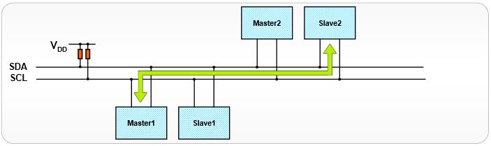
The connection is made via two lines:
- SDA (Serial Data Line) : bidirectional data line,
- SCL (Serial Clock Line) : bidirectional synchronization clock line.
We must not forget the mass that must be common to the equipment.
The 2 lines are pulled at the VDD voltage level through pull-up resistors (RP).
Échange maître esclave
Le message peut être décomposé en deux parties:
- Le maître est l'émetteur, l'esclave est le récepteur:
- émission d'une condition de START par le maître (« S »),
- émission de l'octet ou des octets d'adresse par le maître pour désigner un esclave, avec le bit R/W à 0 (voir la partie sur l'adressage ci-après),
- réponse de l'esclave par un bit d'acquittement ACK (ou de non-acquittement NACK),
- après chaque acquittement, l'esclave peut demander une pause (« PA »).
- émission d'un octet de commande par le maître pour l'esclave,
- réponse de l'esclave par un bit d'acquittement ACK (ou de non-acquittement NACK),
- émission d'une condition de RESTART par le maître (« RS »),
- émission de l'octet ou des octets d'adresse par le maître pour désigner le même esclave, avec le bit R/W à 1.
- réponse de l'esclave par un bit d'acquittement ACK (ou de non-acquittement NACK).
- Le maître devient récepteur, l'esclave devient émetteur:
- émission d'un octet de données par l'esclave pour le maître,
- réponse du maître par un bit d'acquittement ACK (ou de non-acquittement NACK),
- (émission d'autres octets de données par l'esclave avec acquittement du maître),
- pour le dernier octet de données attendu par le maître, il répond par un NACK pour mettre fin au dialogue,
- émission d'une condition de STOP par le maître (« P »).
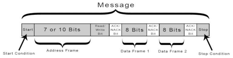
Start Condition: The SDA line switches from a high voltage level to a low voltage level before the SCL line switches from high to low.
Stop Condition: The SDA line switches from a low voltage level to a high voltage level after the SCL line switches from low to high.
Address Frame: A 7 or 10 bit sequence unique to each slave that identifies the slave when the master wants to talk to it.
Read/Write Bit: A single bit specifying whether the master is sending data to the slave (low voltage level) or requesting data from it (high voltage level).
ACK/NACK Bit: Each frame in a message is followed by an acknowledge/no-acknowledge bit. If an address frame or data frame was successfully received, an ACK bit is returned to the sender from the receiving device.
Addressing
I2C doesn’t have slave select lines like SPI, so it needs another way to let the slave know that data is being sent to it, and not another slave. It does this by addressing. The address frame is always the first frame after the start bit in a new message.
The master sends the address of the slave it wants to communicate with to every slave connected to it. Each slave then compares the address sent from the master to its own address. If the address matches, it sends a low voltage ACK bit back to the master. If the address doesn’t match, the slave does nothing and the SDA line remains high.
C'est ainsi que le mot i2c.detect (fin de l'article) détecte les périphériques
connectés au bus i2c.
On peut connecter plusieurs périphériques différents sur le bus i2c. On ne peut pas connecter un même périphérique en plusieurs exemplaires sur le même bus i2c.
I2C port on ARDUINO boards
The I2C port is available in different places depending on the ARDUINO cards.
Port I2C on ARDUINO MEGA board
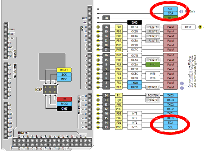
If your card is not a MEGA R3, use only connectors 20 and 21.
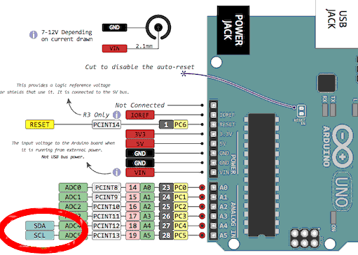
Port I2C on ARDUINO UNO board
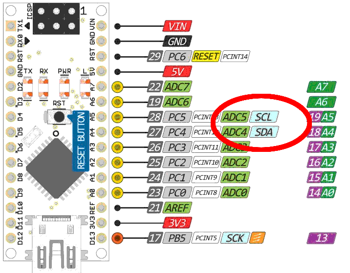
Port I2C on ARDUINO NANO board
Programming the I2C interface
Definition of ports and registers
The ports and registers of the I2C bus are defined beforehand. Addresses ports are valid for all ARDUINO cards:
\ i2c Two-Wire-Interface Registers
184 reg: TWBR   \ TWI Bit Rate register
185 reg: TWSR   \ TWI Status Register
\ 186 reg: TWAR	\ TWI (Slave) Address register - unused
187 reg: TWDR   \ TWI Data register
188 reg: TWCR   \ TWI Control Register
TWBR - TWI Bit Rate register
This register is used in master mode to set the division factor for bit rate generator (SCL clock frequency). The bit rate generator unit controls the time period of SCL. The SCL clock frequency is decided by the Bit Rate Register (TWBR) and the prescaler bits of TWSR register.
The bit rate generator is a frequency divider which generates the SCL clock
frequency in the Master modes.
SCL frequency = CPU clock frequency / (16 + 2 * TWBR * PrescalerValue)
| bit | 7 | 6 | 5 | 4 | 3 | 2 | 1 | 0 |
|---|---|---|---|---|---|---|---|---|
| .. | TWBR7 | TWBR6 | TWBR5 | TWBR4 | TWBR3 | TWBR2 | TWBR1 | TWBR0 |
| read/write | R/W | R/W | R/W | R/W | R/W | R/W | R/W | R/W |
| initial value | 0 | 0 | 0 | 0 | 0 | 0 | 0 | 0 |
TWSR - TWI Status Register
| bit | 7 | 6 | 5 | 4 | 3 | 2 | 1 | 0 |
|---|---|---|---|---|---|---|---|---|
| .. | TWS7 | TWS6 | TWS5 | TWS4 | TWS3 | ------ | TWPS1 | TWPS0 |
| read/write | R/W | R/W | R/W | R/W | R/W | R/W | R/W | R/W |
| initial value | 1 | 1 | 1 | 1 | 1 | 0 | 0 | 0 |
- Bits 7-3 – TWS: TWI Status these bits reflect the status of TWI bus.
- Bit 2Reserved bit
- Bits 1-0TWPS: TWI Prescaler Bits
| TWPS1 | TWPS0 | prescaler value |
|---|---|---|
| 0 | 0 | 1 |
| 0 | 1 | 4 |
| 1 | 0 | 16 |
| 1 | 1 | 64 |
TWAR - (Slave) Address register
Ce registre n'est utilisé que si la carte ARDUINO est utilisée en tant qu'esclave et connectée au bus i2c en liaison avec un périphérique maitre.
| bit | 7 | 6 | 5 | 4 | 3 | 2 | 1 | 0 |
|---|---|---|---|---|---|---|---|---|
| .. | TWA6 | TWA5 | TWA4 | TWA3 | TWA2 | TWA1 | TWA0 | TWGCE |
| read/write | R/W | R/W | R/W | R/W | R/W | R/W | R/W | R/W |
| initial value | 1 | 1 | 1 | 1 | 1 | 1 | 1 | 0 |
TWDR - TWI Data Register
In Transmit mode, This register contains the next byte to be transmitted in transmission mode and in case of receive mode it has last byte received. Note that, it is writable only when the TWI is not in the process of shifting a byte.
| bit | 7 | 6 | 5 | 4 | 3 | 2 | 1 | 0 |
|---|---|---|---|---|---|---|---|---|
| .. | TWD7 | TWD6 | TWD5 | TWD4 | TWD3 | TWD2 | TWD1 | TWD0 |
| read/write | R/W | R/W | R/W | R/W | R/W | R/W | R/W | R/W |
| initial value | 0 | 0 | 0 | 0 | 0 | 0 | 0 | 0 |
TWCR - TWI Conrol Register
| bit | 7 | 6 | 5 | 4 | 3 | 2 | 1 | 0 |
|---|---|---|---|---|---|---|---|---|
| .. | TWINT | TWEA | TWSTA | TWSTO | TWWC | TWEN | ----- | TWIE |
| read/write | R/W | R/W | R/W | R/W | R | R/W | R | R/W |
| initial value | 0 | 0 | 0 | 0 | 0 | 0 | 0 | 0 |
- autoriser l'interruption TWIE
- autoriser le module i2C TWEN: le module prend alors le contrôle physique sur les broches dédiées à l'i2c
- envoi d'un départ (start) TWSTA: doit être remis à 0 par le logiciel quand le start est effectif
- envoi d'un stop TWSTO
- drapeau d'interruption TWINT qui fonctionne comme un drapeau: mis à 0 par écriture d'un 1. Il peut être utilisé pour détecter une fin de transmission. Il faut un "sei()" et TWIE = 1 en supplément pour déclencher une interruption. Cette possibilité de l'utiliser sans interruption fait qu'il n'est pas mis automatiquement à zéro par l'exécution de l'interruption comme certains autres drapeaux.
- autorise l'envoi d'un ack avec TWEA quand une donnée de l'esclave est reçue
\ Bits in the Control Register TWCR
%10000000 constant TWCR_TWINT   \ TWI Interrupt Flag
%01000000 constant TWCR_TWEA    \ TWI Enable Acknowledge Bit
%00100000 constant TWCR_TWSTA   \ TWI Start Condition Bit
%00010000 constant TWCR_TWSTO   \ TWI Stop Condition Bit
%00001000 constant TWCR_TWWC    \ TWI Write Collition Flag
%00000100 constant TWCR_TWEN    \ TWI Enable Bit
%00000001 constant TWCR_TWIE    \ TWI Interrupt Enable
\ bits in the Status Register TWI
%11111000 constant TWSR_TWS     \ TWI Status
%00000011 constant TWSR_TWPS    \ TWI Prescaler
Initializing the I2C bus
The frequency of the SCL is controlled by two registers: TWI Bit rate Register (TWBR) and the prescaler bits in the TWI Status Register (TWSR). The end frequency of SCL is calculated as follows:
- SCL frequency = CPU Clock frequency / (16 + 2 * (TWBR) * (Prescaler)
- TWBR is at $b8
TWSR is at $b9 and the prescaler bits are 0 and 1. The prescaler value is as follows:
| TWSR 1 | TWSR 0 | Prescaler value |
|---|---|---|
| 0 | 0 | 1 |
| 0 | 1 | 4 |
| 1 | 0 | 16 |
| 1 | 1 | 64 |
So. Assuming a 16 MHz clock, if you wanted to have the TWI run at 100kHz, you could use the prescaler value of 4, and a bit rate register value of 18. If you wanted to jack that up to 400kHz, you could quadruple the value of TWBR, or you could use the next prescaler value. Just make sure that whatever you're talking to supports the speed you're wanting to run it at.
: i2c.init ( -- )               \ Set clock frequency to 100kHz
    TWSR_TWPS TWSR mclr         \ prescale value = 1
    [ Fcy 100 / 16 - 2/ ] literal TWBR c!
    %00000011 TWCR mset TWCR mset
  ;
Protocoles du bus I2C
Le dialogue se fait uniquement entre un maître et un esclave.
Le dialogue est toujours initié par le maître (condition Start): le maître envoie sur le bus I2C l'adresse de l'esclave avec qui il veut communiquer.
Le dialogue est toujours terminé par le maître (condition Stop).
Le signal d'horloge (SCL) est généré par le maître.
Le mot i2c.wait vérifie que le bus I2C est libre.
: i2c.wait ( -- ) \ Wait for operation to complete
    \ When TWI operations are done, the hardware sets
    \ the TWINT interrupt flag, which we will poll.
    begin
        TWCR c@ TWCR_TWINT and
    until
  ;
Le mot i2c.start initie le dialogue maitre vers esclave.
: i2c.start ( -- ) \ Send start condition
    [ TWCR_TWINT TWCR_TWEN or TWCR_TWSTA or ] literal TWCR c!
    i2c.wait
  ;

: i2c.rsen ( -- ) \ Send repeated start condition
    i2c.start     \ AVR doesn't distinguish
  ;
Le mot i2c.stop termine le dialogue maitre vers esclave.
: i2c.stop ( -- ) \ Send stop condition
    [ TWCR_TWINT TWCR_TWEN or TWCR_TWSTO or ] literal TWCR c!
  ;
Ecriture et lecture sur le bus I2C
\ Write one byte to bus, returning 0 if ACK was received, -1 otherwise.
: i2c.c! ( c -- f )
    i2c.wait \ Must have TWINT high to write data
    TWDR c!
    [ TWCR_TWINT TWCR_TWEN or ] literal TWCR c!
    i2c.wait
    \ Test for arrival of an ACK depending on what was sent.
    TWSR c@ $f8 and $18 xor 0= if   0 exit  then \ SLA+W
    TWSR c@ $f8 and $28 xor 0= if   0 exit  then \ data byte
    TWSR c@ $f8 and $40 xor 0= if   0 exit  then \ SLA+R
    -1  \ Something other than an ACK resulted
;

\ Read one byte and ack for another.
: i2c.c@.ack ( -- c )
    [ TWCR_TWINT TWCR_TWEN or TWCR_TWEA or ] literal TWCR c!
    i2c.wait
    TWDR c@
  ;

\ Read one last byte.
: i2c.c@.nack ( -- c )
    [ TWCR_TWINT TWCR_TWEN or ] literal TWCR c!
    i2c.wait
    TWDR c@
 ;
\ Address slave for writing, leaving true if slave ready.
: i2c.addr.write ( 7-bit-addr -- f )
    1 lshift 1 invert and \ Build full byte with write-bit as 0
    i2c.start i2c.c!
    if      false
    else    true    then
  ;

\ Address slave for reading, leaving true if slave ready.
: i2c.addr.read ( 7-bit-addr -- f )
    1 lshift 1 or \ Build full byte with read-bit as 1
    i2c.start i2c.c!
    if      false
    else    true    then
  ;
Ping de périphérique I2C
\ Detect presence of device, leaving true if slave responded.
\ If the slave ACKs the read request, fetch one byte only.
: i2c.ping? ( 7-bit-addr -- f )
    1 lshift 1 or     \ Build full byte with read-bit as 1
    i2c.start i2c.c! 0=
    if
        i2c.c@.nack drop true
    else
        false
    then
  ;
Detecting an I2C device
This part is used to detect the presence of a device connected to the I2C bus.
You can compile this code to test the presence of connected and active modules on the I2C bus.
: device.detect ( n ---)
    i2c.ping? \ does device respond?
    if      dup 2 u.r
    else    ." -- "
    then
  ;


\ not all bitpatterns are valid 7bit i2c addresses
: i2c.7bitaddr? ( a --)
    $07 $78 within
    if      dup device.detect
    else    ."    "
    then
  ;

\ display header line
: disp.0line ( ---)
    cr
    ."      00 01 02 03 04 05 06 07 08 09 0a 0b 0c 0d 0e 0f"
  ;

: start.line? ( n ---)
    $0f and 0=
    if      cr dup 2 u.r ." : "
    then
  ;

: i2c.detect   ( -- )
    i2c.init
    base @ hex
    disp.0line  \ header line
    0 $80
    for
        dup start.line?
        dup i2c.7bitaddr?
        1+
    next
    drop
    cr base !
    i2c.stop
  ;
In order for i2c.detect to be executed first i2c.init.
Then, we can execute i2c.detect:
i2c.init  ok<#,ram>
i2c.detect
     00 01 02 03 04 05 06 07 08 09 0a 0b 0c 0d 0e 0f
00 :                      -- -- -- -- -- -- -- -- --
10 : -- -- -- -- -- -- -- -- -- -- -- -- -- -- -- --
20 : -- -- -- -- -- -- -- -- -- -- -- -- -- -- -- --
30 : -- -- -- -- -- -- -- -- -- -- -- -- -- -- -- --
40 : -- -- -- -- -- -- -- -- -- -- -- -- -- -- -- --
50 : -- -- -- -- -- -- -- -- -- -- -- -- -- -- -- --
60 : -- -- -- -- -- -- -- -- 68 -- -- -- -- -- -- --
70 : -- -- -- -- -- -- -- --
 ok <#,ram>
Here, we detected a module at the hexadecimal 68 address. It's this
address that we will use to address this module:
Management of the RTC DS1307 module