Controlling a NEMA14 motor with the A4988 driver
published: 27 October 2020 / updated 27 October 2020

Preamble
This article results from a question asked on Facebook in the group ARDUINO FORTH.
The member who asked the question was struggling with a FORTH language code inspired by a C language library.
After analyzing the code in C language, it turns out that this control library for an engine step by step suffers from several problems:
- no explanation on the operating diagram of the A4988 driver
- a thick code that wants to exploit a lot of parameters and possibilities...
Voir cette librairie: Stepper library for Wiring/Arduino.
L'inconvénient de ce type de librairie, en l'utilisant pour son projet ARDUINO, c'est de téléverser la totalité du code de cette librairie sur la carte ARDUINO.
With the FORTH language, we will again use a bottom-up development strategy, called bottom-up. We will first look for the characteristics of the material used. Then we write the code FORTH specifically adapted to this material.
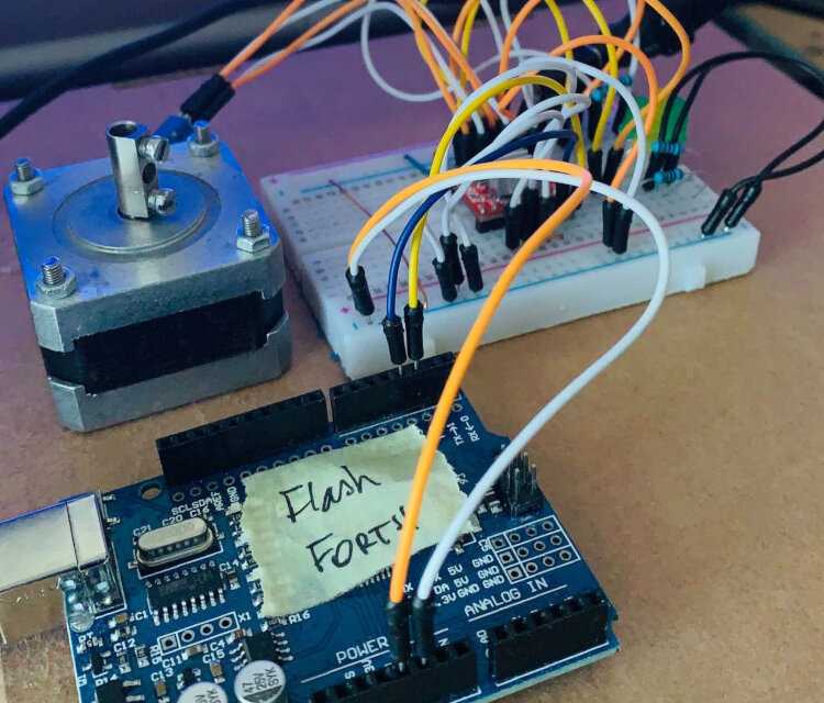
Equipment used
Necessary material:
- an ARDUINO UNO, NANO or MEGA card, with FlashForth installed on it
- an A4988 stepper motor driver board
- a NEMA14 bipolar stepper motor
A4988 Stepper Motor Control Module
This module has the ability to drive the stepper motor with only two control wires from the ARDUINO card.
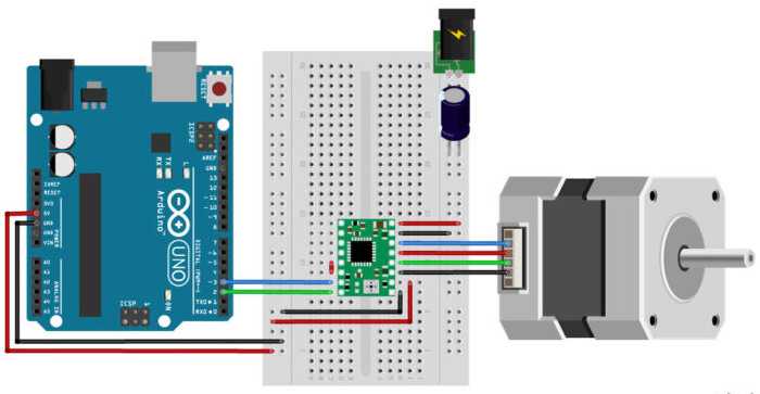
This module is installed between the ARDUINO card and the stepper motor as in this diagram:
NEMA14 stepper motor
It is a stepper motor with high torque. It is ideal for ordering equipment requiring precise positioning.
To avoid the risk of destroying the ARDUINO card, the A4988 module and the stepper motor not NEMA14 must be powered by an independent power source.
The stepper motor control program
To use the FORTH code which follows, it is first necessary to compile the contents of the file ARDUINO pins definitions
Physically, the A4988 module is connected to the ARDUINO card with only two wires:
- DIR (DIRECTION) pin from A4988 to PD2 pin of the ARDUINO UNO board (green wire on the diagram)
- STEP pin from A4988 to PD3 pin (blue wire on the diagram
As a reminder, PD2 is the shortened form of Port D bit 2... which already allows us to declare port D and the connectors that interest us:
decimal
flash
43 constant PORTD
PORTD %00000100 defPIN: DIRECTION
PORTD %00001000 defPIN: PULSE
ram
The words DIRECTION and PULSE are similar to
constant. Each of these words stacks the binary mask and the port concerned when
they are executed. In the following code, we go up or down the logic level on
PD3 simply with the sequence PULSE high or PULSE low:
\ pulse delay
10 value pulseDelay

\ send one pulse to step motor
: impulse ( ---)
    PULSE high
    pulseDelay ms
    PULSE low
    pulseDelay ms
 ;
The execution of the word impulse puts PD3 pointed to by
PULSE high, then low, with a time delay of 10 milliseconds. To modify
this time delay, all you have to do is modify the content of the pulseDelay value.
We must now control the direction of rotation of the motor, by acting on the
pin PD2 pointed to by DIRECTION:
\ select Clock Wise rotation
: setCW ( ---)
    DIRECTION high
  ;

\ select Counter Clock Wise rotation
: setCCW ( ---)
    DIRECTION low
  ;

: setDirection ( n ---)
    0<
    if      setCCW
    else    setCW
    then
  ;
The word setCW selects the direction of rotation clockwise: CW = Clock Wise.
The word setCCW selects the direction of rotation in the opposite clockwise direction: CCW = Counter Clock Wise.
The two words setCW and setCCW are used in the definition of the word
setDirection which gets the number of steps to be executed by the stepper motor. If this
value is positive, the motor rotates clockwise, if this value is negative, the motor
turns in the opposite direction. Example: 200 setDirection ....
And already, we arrive at the definition that will allow the stepping motor to run:
: steps ( n ---)
    dup setDirection
    abs
    for
        impulse
    next
  ;
The number of steps is duplicated in steps to determine the direction of rotation.
Then, we transform this number of steps into a positive value which will be used to determine
the number of iterations of the for..next loop.
By the way, the factorization of the FORTH code allows great readability, on the one hand, then a real compactness of definitions.
All of this would not work without initializing the ports:
: init.stepper ( ---)
    DIRECTION output
    PULSE     output
  ;
And to test it all:
\ test stepper motor
init.stepper
200 steps
Here on Facebook: the video with the engine running
Conclusion
This code can evolve to increase the rotation speed, manage acceleration ramps and stepper motor deceleration. But that's another story.
What is important to remember is the development approach:
- from retail to general, bottom-up strategy, known as bottom-up. We take care first of all the most discreet mechanisms before including them in definitions more general
- we factorize the code with words as explicit as possible. Definitions
short and simple. For example, for words like
DIRECTION, if you want use another terminal on a different port, there are just two lines of code to adjust.
And finally, interesting detail, all the FORTH code was developed without having access to the hardware to test it.
The end user grabbed this code, compiled it and tested it successfully, requiring a simple
time delay adjustment in pulseDelay.
The full listing is available here: Controlling a NEMA14 motor with the A4988 driver