Operation of the UART0 serial port on ARDUINO cards
published: 1 December 2020 / updated 1 December 2020
Role of the serial port with FlashForth on ARDUINO cards
During the development and debugging phase, the ARDUINO card communicates with the terminal via a USB link:
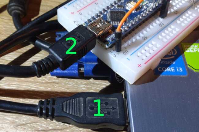
In the photo:
- card marked "1": USB serial port of the PC managed and used by the terminal (TeraTerm for example)
- plug marked "2": USB serial port of the ARDUINO card (here ARDUINO NANO card)
Any character typed at the terminal is displayed on the terminal. Simultaneously, this character transits by the ARDUINO card and FlashForth.
Pressing the ENTER key on the PC side causes the interpretation of any sequence of characters transmitted to the ARDUINO card.
The tx0 and rx0 primitives
ARDUINO NANO and UNO cards have only one serial port. Here in red for the map ARDUINO NANO:

These ports are replicated on the USB socket. Clearly, any character received or transmitted on D1/TX or DO/RX is equivalent to that received or transmitted via the USB port.
The D1/TX and DO/RX ports are managed by the words tx0 and rx0.
If you do:
64 tx0
is equivalent to:
64 emit
The word emit is the standard word in the FORTH language for emitting a character.
Likewise, the word key is the standard word for receiving a character.
Vectors for transmitting and receiving characters
The management of sent and received characters is managed by three words:
- emit using the contents of the user variable
'emitand pointing totx0 - key using the contents of the user variable
'keyand pointing torx0 - key? using the contents of the user variable
'key?and pointing torx0?
To modify the behavior of emit we will act on its vector 'emit. In our
article titled:
Broadcast text on the 128x32 monochrome OLED display
a character is transmitted to the SSD1306 OLED display using the word char.tx. As a reminder, its definition:
\ Draw character:
: char.tx ( c --)
    \ if 'cr' go to next line
    dup $0d =
    if
        crLine drop
        exit
    then
    \ otherwise, display character
    addrSSD1306  i2c.addr.write drop \ send SSD1306 address
    CTRL_DATAS i2c.tx
    a>bp        \ start addr
    5
    for
        c@+     \ get byte and inc addr
        i2c.tx  \ transmit byte
    next
    drop
    $00 i2c.tx  \ transmit 'blank'
    i2c.stop
  ;
To modify the behavior of emit, we will simply act on
the content of its 'emit vector like this:
' char.tx 'emit !
We can then write in FORTH a definition that writes data on the OLED screen using standard words from the FORTH dictionary:
: .scores ( --)
    ." -- YOUR SCORES: --" cr
    ." Allan   : " 36 . cr
    ." Mike    : " 42 . cr
    ." ..press BUTTON..."
  ;
Running .scores will display the text and data on the OLED screen:
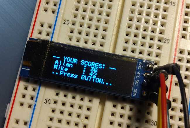
I know, I know, that sounds magical. But don't applaud! I'll blush ... It's only FORTH!
Connecting a device to the serial port
To understand how the serial port works on ARDUINO cards, we will start
by connecting a device to this serial port. But we are not going to use just any
serial device. We announce connect
The TTL/serial converter CP2102
like this:
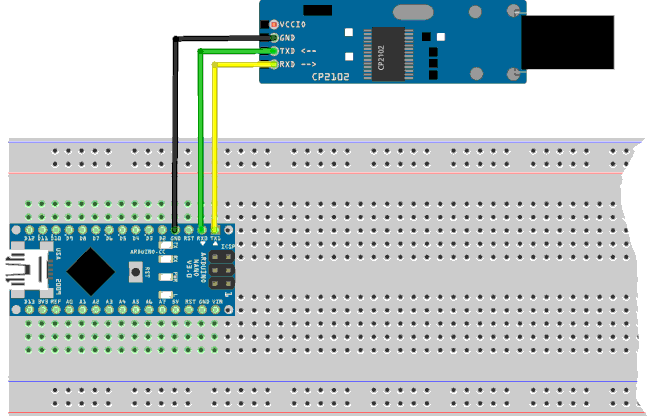
Then we connect our ARDUINO NANO card to a USB port, the TTL/serial converter CP2102 to another USB port.
Finally, we open two windows from the TeraTerm terminal:

Here, the left window corresponds to the USB connection to the ARDUINO NANO card.
The window on the right is that of the USB link to the TTL / serial converter CP2102, which is connected to the port series of our ARDUINO NANO board. So we have two different inputs on this serial port.
Let's place the cursor in the left window. Let's try to type something and press the ENTER key. Nothing is happening. It is as if the USB port communicating with the ARDUINO NANO card is not working.
Now let's place the cursor in the window on the right. There, if we type something, this strike appears in both deneters!
So, via the USB port and the TTL / serial converter CP2102, we access the FlashForth interpreter exactly in the same way as if we communicated with the only USB port of the ARDUINO NANO card. Here's what's going on:
- a character is typed in the window of the serial link terminal via the TTL / serial converter CP2102;
- this character is received by the serial port of the ARDUINO card;
- it is captured in FlashForth's serial buffer which then echoes it on the serial port;
- this character is displayed in both terminal windows.
If we replace our TTL / serial converter CP2102 by another type of terminal on this serial port, a LoRa transmitter for example, we will have exactly the same behavior.
To properly use our serial port with a serial peripheral other than the terminal, we must therefore develop a serial communication strategy that does not conflict with the interpreter by FlashForth.
Control of character emission
The best strategy, to avoid conflicts in sending and receiving characters on the serial port consists in controlling the emission of characters.
In order to illustrate this strategy, we start by compiling these definitions using the window on the right of the TeraTerm terminal:
\ create a string variable
: string  ( n --- names_strvar)
    create
        dup
        c,      \ n is maxlength
        0 c,    \ 0 is real length
        allot
    does>
        2 +
        dup 1 - c@
  ;

eeprom
64 string rxBuffer
ram

\ input from serial rx0 in rxBuffer
: rx0Input  ( ---)
    rxBuffer drop dup
    dup 2- c@ accept swap 1- c!
  ;
We test the correct operation of the character entry:
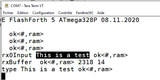
The word rx0Input expects the input of up to 64 characters. If this seizure
is interrupted by pressing the ENTER key, the sisie stops. Here, in our image, we
entered the text This is a test, then press the ENTER key.
he rxBuffer type sequence allows you to see the content stored in our
text variable rxBuffer.
The problem, if you use a device of the Lora transmitter type, is that everything
message deposited in our buffer rxBuffer by the peripheral in serial link
will emit these characters, therefore receive them, therefore generate an error code, which will generate
again an error code, etc...
We are going to use vectorization again, by creating a word emit-:
: emit- ( ---)
    ['] drop 'emit ! ;
The word emit- will inhibit the echo of the entry in the buffer rxBuffer.
In order not to block any other emission of characters, we define another word emit+
responsible for restoring the emission of characters:
: emit+ ( ---)
    ['] tx0 'emit ! ;
Finally, to illustrate the use of the words emit- and emit+, we do a test:
: test ( ---)
    begin
        emit-
        rx0Input
        emit+
        rxBuffer type
    again
  ;
Running test takes us into an infinite loop of
seizures. Each entry is displayed after pressing the ENTER key:
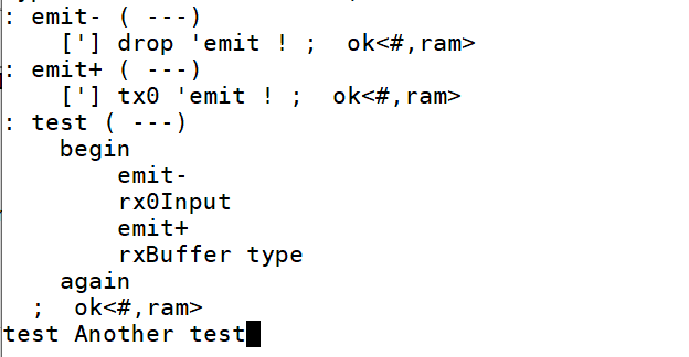
Here we just typed Another test, but no echo on the terminal.
Our goal has been achieved: to be able to receive and transmit on the serial port without the reception does not interfere with the emission of characters.
Management of transmission to a serial device
Our ARDUINO NANO card is connected to a serial peripheral, without connection with a terminal via its USB port.
The operation of our application is organized as follows:

The best strategy is to allow the emission of characters in the phase
send response. If we manage a display device, our OLED display
for example, which is on an I2C link, the text to be displayed will be transmitted with
a vectorization specific to this display, for example with the word toOLED
which could be defined as:
: toOLED ( ---)
    ['] char.tx 'emit ! ;
Here, the word toOLED will allow the transmission of characters
to the OLED display. As this transmission no longer passes through the serial port,
there will be no risk of interference with the serial device.
Good programming.
