Time measurement by TIMER
published: 2 October 2020 / updated 2 October 2020

This article is inspired by the msecTimer.ff program produced by Klaus KUENEL:
Custom Timer Functions on Arduino Nano
La mesure du temps est une nécessité qui revient fréquemment en programmation:
- tester le temps d'exécution d'une partie de programme;
- imposer un délai entre deux déclenchement d'une fonction;
- mesurer le temps dans le traitement d'un signal, par exemple pour un radar à ultrasons???
Tous les mots FORTH sont conçus et testés pour la carte ARDUINO NANO. Le code est valable pour ARDUINO NANO et ARDUINO MEGA.
The wrong way to measure elapsed time
The wrong way to estimate the elapsed time for a process is to appeal to a variable whose content is incremented by a function:
variable nbCounts
: incCounts  ( -- )
    1 nbCounts +! ;  \ increment 1 unit content of nbCounts
: test01  ( -- )
    0 nbCounts !
    begin
        incCounts
        key?         \ continue if no key pressed on keyboard
    until
    nbCounts @ .     \ display content of nbCounts
  ;
It may be suitable for certain uses. But why is this the wrong way? It's a bad way:
- the
msfunction (tempo in milliseconds) will alter the regularity of the counting; - does not allow counting if the counting increment is not integrated into the definition of a word;
A much better idea would be to go through an independent multitasking process
taking care of incrementing the content of our variable nbCounts.
In fact, the microcontrollers fitted to the ARDUINO boards are equipped with timers which can be exploited via software interrupts.
The good idea is therefore to exploit a TIMER interrupt acting on the content of a count variable.
The advantage of a timer to count the elapsed time is that the program can achieve something else during this time.
Les registres TIMER pour ARDUINO NANO
To realize exact timing Arduino has several timers which can be used with interrupts.
Timer0 is used for ms. Timer 1 is used for the CPU load measurement. Timer2 is free.
In this article, we use Timer2 to generate a 10 ms output compare interrupt which increments a variable counter each 10 ms.
Un timer est un registre à l’intérieur du microcontrôleur qui s’incrémente (ou se décrémente) chaque fois qu’il reçoit une impulsion d’un signal d’horloge. Ce signal d’horloge peut être propre au microcontrôleur ou bien extérieur à celui-ci. Un timer est donc un compteur capable de compter le temps qui s’écoule, d’où son nom anglais de timer counter.
Le tableau suivant donne les différents registres de contrôle associés à chaque timer.
| Timer 0 | Timer 1 | Timer 2 | rôle / role |
|---|---|---|---|
| TCNT0 | TCNT1L | TCNT2 | Timer (bit 0 à 7) |
| - | TCNT1H | - | Timer (bit 8 à 15) |
| TCCR0A | TCCR1A | TCCR2A | Registre de contrôle |
| TCCR0B | TCCR1B | TCCR2B | Registre de contrôle |
| - | TCCR1C | - | Registre de contrôle |
| OCR0A | OCR1AL | OCR2A | Output Compare (bit 0 à 7) |
| - | OCR1AH | - | Output Compare (bit 8 à 15) |
| OCR0B | OCR1BL | OCR2B | Output Compare (bit 0 à 7) |
| - | OCR1BH | - | Output Compare (bit 8 à 15) |
| - | ICR1L | - | Input Capture (bit 0 à 7) |
| - | ICR1H | - | Input Capture (bit 8 à 15) |
| TIMSK0 | TIMSK1 | TIMSK2 | Interrupt Mask |
| TIFR0 | TIFR1 | TIFR2 | Interrupt Flag |
Signification des abbréviations
- TCNT Timer/Counter (Register)
- TCCR Timer/Counter Control Register
- OCR Output Compare Register
- ICR Input Capture Register
- TIMSK Timer/Counter Interrupt Mask Register
- TIFR Timer/Counter Interrupt Flag Register
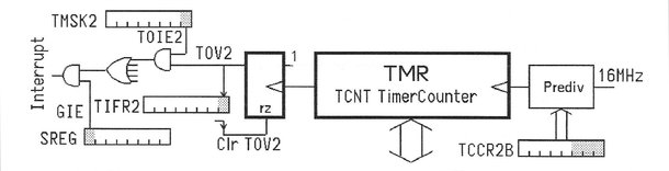
Les registres TCCR2A, TCCR2B et TIMSK2
TCCR2A - Timer/Counter2 Control Register A
| bit | 7 | 6 | 5 | 4 | 3 | 2 | 1 | 0 |
|---|---|---|---|---|---|---|---|---|
| COM2A1 | COM2A0 | COM2B1 | COM2B0 | ---------- | ---------- | WGM21 | WGM20 |
TCCR2B - Timer/Counter2 Control Register B
| bit | 7 | 6 | 5 | 4 | 3 | 2 | 1 | 0 |
|---|---|---|---|---|---|---|---|---|
| FOC2A | FOC2B | ---------- | ---------- | WGM22 | CS22 | CS21 | CS20 |
Pour ralentir un timer, il suffit d'utiliser le prédiviseur pour diviser la fréquence du signal d'horloge. Pour faire cela, il suffit de positionner certains bits du registre TCCR2B
TIMSK2 - Timer/Counter Interrupt Mask register
| bit | 7 | 6 | 5 | 4 | 3 | 2 | 1 | 0 |
|---|---|---|---|---|---|---|---|---|
| ---------- | ---------- | ---------- | ---------- | ---------- | OCIE2B | OCIE2A | TOIE2 |
Rôle du registre OCR2A
On peut charger un nombre dans le registre OCR2A. Quand le timer 2, en comptant, devient égal à OCR2A, ça provoque la mise à 1 d’un flag appelé OCF2A. Si on a autorisé les interruptions, ce flag va commander une interruption qui sera traitée par la routine d'interruption.
\ Disable interrupt before removing the interrupt code
T2_COMPA_Dis

-msectimer
marker -msectimer

\ Timer2 Register Definitions
$b0 constant TCCR2A
$b1 constant TCCR2B
$70 constant TIMSK2
$b3 constant OCR2A

\ counter incremented by interruption
variable counter

\ Interrupt routine for Timer1 CompareA
: T2_COMPA_ISR
    1 counter +!
  ;i

#8  constant OC2Aaddr \ interrupt vect no 8
: setupInt  ( -- )
    ['] T2_COMPA_ISR OC2Aaddr int!
  ;


\ display content TIMERs registers
: dispRegs ( -- )
    hex
    cr ." OCR2A:  " OCR2A  c@ 2 u.r
    cr ." TCCR2A: " TCCR2A c@ 2 u.r
    cr ." TCCR2B: " TCCR2B c@ 2 u.r
    cr ." TIMSK2: " TIMSK2 c@ 2 u.r
    cr
    decimal
  ;

\ OCR2A Reload for 10 ms@16 MHz clock & prescaler 256
$9c constant RELOAD

\ general setup TIMER 2
: setupTimer ( -- )
    0 TCCR2B c!       \ Stop Timer2
    RELOAD OCR2A c!   \

    0 counter !
    setupInt

    %0010 TCCR2A c!   \ CTC Mode
    %0111 TCCR2B c!   \ Prescaler = 1024
    %0010 TIMSK2 c!   \ Timer2 CompareA Interrupt enable
    dispRegs
  ;


\ Disable interrupt before removing the interrupt code
: T2_COMPA_Dis
    1 TIMSK2 mclr
  ;