An industrial automaton with fractal matrix
published: 6 December 2019 / updated 6 December 2019

Preamble
Binary coding is sometimes amazing, often full of resources. The following subject shows how to master binary coding very simply in a very concrete case: the management industrial storage on assembly line ...
The storage management principle explained here was designed and operated in the years 1992-1998. It was programmed in FORTH language with the TURBO-Forth version under MS-DOS 3.0. The application was mounted in a PC without hard disk, with a 128 KB dynamic memory, running on batteries where was stored MS-DOS and the program managing the industrial automat.
The configuration of the PLCs was carried out using a simple text editor. The file parameterization was stored on a floppy disk, copied to the battery space of the PLC and read by the PLC at each start.
When reading the rest of the article, you will understand, I hope, the immense advantage of the FORTH language compared to any other programming language.
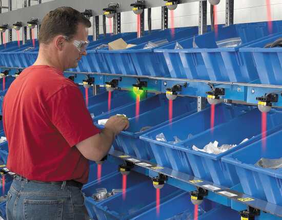
The purpose of the project at the time was simply to light a lamp over a locker of storage when a part had to be taken in the storage rack and mounted on an automobile.
The controller should avoid mounting errors, errors that generated end-of-line times, sometimes expensive mistakes in after-sales follow-up ...
The Japanese auto industry already had its solutions, say POKA YOKE (anti-error). Article Wikipedia: Détrompeur.
Here Seven Wastes – Defects an other article
of a company that operates this type of system. Extract: Many methods are available to help fix or
catch defects. A popular in-process system is a Poka-yoke. An example of a poke yoke can be
a pick to light system, a photo verification system, or a go/no go system.
Bottom-up design
The programming approach is ascending (bottom-up). This approach aims first of all at deal with the problem in a fine way in the management of the storage array.
At the time, three engineers had been working for a month on a solution to keep up with 128 KB of disk space (battery memory). Their pre-study was trying to define how to manage the boxes, so with a graphical interface, graphics limited to the possibilities of text mode under MS-DOS.
The approach of these engineers was a down (top-bottom) approach. This approach ran into how to interface the data management part to the signal lamp management part.
When I took the project in hand, I left totally zero. I only had as point ed departure the constraints of management of signal lamps.
Fractal matrix coding
The idea is to build a matrix of first level L0, in a Euclidean space, thus with two axes: X and Y. On each of these axes, one can only have two values: 0 or 1. Which gives the following organization of our matrix L0:

The position of the blue box can be indicated by the pair XY which will have as value 10 in binary, 2 in decimal.
Definition of a higher level
Three L0 level copies are created as follows:

The position of each level matrix L0 can be identified by an XY pair. Here, the matrix L0 where the blue box is located is marked at level L1 by the pair XY of value 11. The blue box is identified by the pairs 1110.
If an 8-bit group is one byte, let's name a 2-bit group DUET.
In the identification of the blue box of the drawing above, this position is identified with the help of two duets:
- duet of low weight on the right, value 10
- most significant duet left, value 11
If we group two duets, we get a quartet. Identification of each level box L0 by quartet:

With a quartet, we are able to address any box among 16 boxes in a 4x4 size L1 array.
If each level could be addressed by logical gates, two wires would suffice to indicate in X and two wires in Y the L1 level selection and the relevant box 1001 in the L0 level:

On this diagram, in the left part, we have two sons to activate the selection in the row: yL1 and yL0. Two bits are enough to control this selection. Here, the values that operate yL1 = 0 and yL0 = 1.
It is the same for the selection in X that is not schematized. But the principle is the same.
Practical application
The industrial application that exploited this fractal addressing technique was a system 'pick to light'.
The POKA YOKE system installed in the automotive industry was programmed in FORTH.
To manage more boxes, just increase the number of levels. For example, by adding a new level L2, we increase the number of boxes by a factor of 4. With three levels, L0, L1 and L2 we can manage 64 boxes:

Here, the yellow box is activated by the sequence 100111.
If we add a level L3, we can manage 256 boxes. A single byte would designate a single lamp in this 16x16 matrix.
As you begin to understand, the Lx -> Lx-1 nesting scheme is similar. We can say that this nesting scheme is FRACTAL!
Let's go back to our module of 64 boxes including 3 levels. To light a lamp among 64 lamps, you only need 6 control wires, which is within the reach of any ARDUINO board.
Each group of boxes is designated as module
. Each module is independent of
other. In the rest of this article, we will only deal with the case of a single module of 64 boxes.
And FORTH in all this?
The trick was to find the way to code a position in X and Y, here X=5 and Y=2, in a binary combination directly transmittable to the automaton.
On the automobile assembly line, where the car radios are placed, it was necessary that the operator mounts the model requested by the customer, among dozens of models.
A SONY DSXA 21 car radio was identified in row 4, column 6 ( yellow box).
At initialization, it was imperative to reliably translate these coordinates (x:4|y:6) into a binary sequence directly injectable into the automaton.
Let's take coordinates such that the operator sees them: (x:6|y:4).
The ordinal values we wish to exploit must start from 0. So we will subtract 1 from each of these coordinates, which gives us (x:5|y:3). This is what we see in the picture above.
Each ordinal value X and Y will be in the range [0..7]. That we arrange, because we can hold X or Y on 3 bits only.
But before getting into FORTH coding, let's see the activation code
the yellow box that is 100111.

The activation bits X of the L2, L1 and L0 levels are black-colored. They are grouped, which gives the binary value 101, which is 5 in decimal!
The activation bits Y of levels L2, L1 and L0 are colored in red. They are grouped, which gives the binary value 011, which is 3 in decimal!
We find our values (x:5|y:3)...!!!
Decoding of the activation frame
The code presented here has been adapted for FlashFORTH on ARDUINO. This is by no means the original code of the industrial automaton, which is much more complex, and dates from 1992.
We start by defining some variables and how to initialize them:
-xy
marker -xy
variable XY
variable X
variable Y
: XY.set ( xy ---)
    XY !
   ;
%100111 XY.set
Here we gave the value %100111 XY.set for
check if the code works well. The XY variable receives
always the activation code to decode.
We will now decode the X and Y values:
: X.decode ( --- x )
    0 X !               \ initialise X values
    XY @ %00000010 and
    if  1 X +!   then
    XY @ %00001000 and
    if  2 X +!   then
    XY @ %00100000 and
    if  4 X +!   then
    X @
  ;
: Y.decode ( --- x )
    0 X !               \ initialise Y values
    XY @ %00000001 and
    if  1 X +!   then
    XY @ %00000100 and
    if  2 X +!   then
    XY @ %00010000 and
    if  4 X +!   then
    X @
  ;
The goal is not to make a well factored code, but an efficient and simple code.
That's why we preferred to use variables rather than stack manipulations.
Take the code X.decode: we just do a test on the bits b1 b3 and b5.
If the test results are not zero, we add 1 2 and 4 to the value of the variable X.
It remains to decode XY like this:
: XY.decode ( xy --- x y)
    XY.set
    X.decode
    Y.decode
  ;
We test XY.decode:
%00100111 XY.decode . . \ display 3 5
Encryption of the activation frame
Now, let's see how to encode a lamp activation frame from its only X and Y coordinates:
: X.encode ( x --- Lx )
    0 X !
    dup %00000001 and
    if  2 X +!   then
    dup %00000010 and
    if  8 X +!   then
        %00000100 and
    if 32 X +!   then
    X @
  ;
: Y.encode ( x --- Lx )
    0 Y !
    dup %00000001 and
    if  1 Y +!   then
    dup %00000010 and
    if  4 Y +!   then
        %00000100 and
    if 16 Y +!   then
    Y @
  ;
Again, the goal is not to create an optimized code, but a scratch form
(rough formwork) simple and effective and easy to develop.
And now the word XY.encode that will encode our X and Y coordinates into a
lamp activation frame:
: XY.encode ( x y --- xy)
    0 XY !
    Y.encode
    X.encode  or  XY !
    XY @
  ;
We test the word XY.encode:
5 3 XY.encode .    \ display 39
39 bin .           \ display 100111
decimal
At this point, our definitions in FORTH language, once compiled on the ARDUINO card, occupy 652 bytes!
Hey yes! In less than 1 kilobyte we already have essential definitions managing a stock of products for processing by a POKA YOKE type system.
Storage of products in stock
And now, we are going to put away our stock. As an example, we will put car radios in the boxes. To do this, we will first define a new definition word:
: defCELL: ( x y --- <mot>)
    XY.encode
    create
        ,
    does>
        @
  ;
The word defCELL: takes as parameters the X and Y storage values. Those data
X and Y are ordinal values starting at zero. If you want to process ordinal values
starting at 1, I let you adapt the code.
We will store two separate brands of car radios in two separate boxes:
eeprom
5 3 defCELL: SONY-DSXA-21
4 2 defCELL: AIWA-452C
ram
It is childlike simplicity We indicate the position X and X followed by the word defCELL:
and the word to create. Here we create two words: SONY-DSXA-21 and AIWA-452C.
These words SONY-DSXA-21 and AIWA-452C are treated almost like constants.
Only advantage, to turn on the lamp that is in X: 5 and Y: 3, just indicate the
word designating the product, for example AIWA-452C followed by the lamp activation word...
We are not going to define this lamp activation word. This is not the subject of this article.
What's interesting is that to fill our module with 64 boxes, just define the 64 products on the model x y defCELL: product.
Find a stored product
When you have a lot of products, it can be useful to create a word
cell? who will find us this product in the stock:
: cell? ( xy ---)
    XY.decode
    cr ." Row: " .
    cr ." Col: " .  cr
  ;
And that is used simply like this:
AIWA-452C cell?
\ display:
\ Row: 2
\ Col: 4
\  ok<#,ram>
We summarize: to store products, we create as many words as there are products to store, simply by indicating their position in the module.
So, no table, no list, nothing ...
In reality, in the original POKA YOKE type application, there was still a table, which stored the words defined as and when, with the reference of the code transmitted by the factory network or the barcode reader.
Conclusion
FORTH language allows to create perfectly operational prototypes of complex mechanisms. Our example comes from a real application. We only take back the basic concept.
There are two key points:
- a bottom-up approach, starting from the most to exploit them more globally;
- priority is given to operational operation before ergonomics.
- it's as simple as possible ...
This approach made it possible, in 1992, to present a first draft of a POKA YOKE type 'pick to the light', developed alone in less than a week. The version original included BALOGH network management (BALOGH industrial network), management of a barcode reader, communication with the relay cards via a loop of current at 100 Kbps, all in multi-task ...
What particularly appealed to the end customer is the fact that they can manage the define stock in modules from any text editor, including on the automat itself! TURBO-Forth was provided with a publisher text, written in FORTH, which occupied 16 KB on the 'RAM disk'.
The first delivery was full of tests. Intervention directly and recompile in less than two minutes the entire application was a main quality.
In its most expanded version, the FORTH application could handle 600 boxes in less than 300 milliseconds, on a PC clocked at 10 Mhz.
A current ARDUINO card uses a RISC processor clocked at 16 Mhz. These cards are therefore potentially 4 to 10 times faster than the PCs of the time.
The company that sold the final POKA YOKE product has multiplied its capitalization by 6 in a decade. This society still exists. It does not operate anymore FORTH ... to our knowledge.