Control a LED by PWM in 176 bytes
published: 23 April 2020 / updated 10 June 2020

Preamble
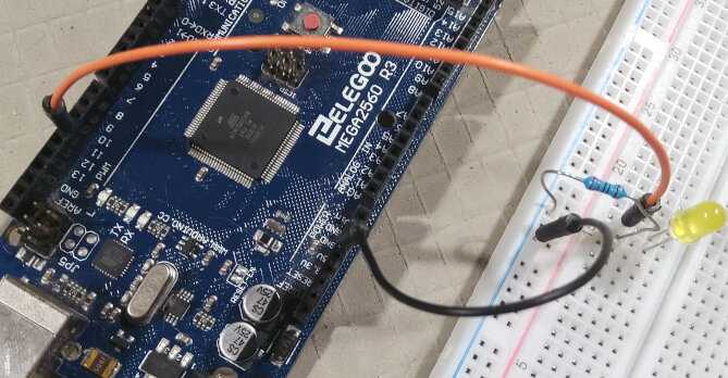
Connection of the LED to the ARDUINO card:
We will immediately show the program that manages the brightness of an LED by PWM:
\ PWM LED Driver

36 constant DDRB
\ Timer/Counter1 Control Register
128 constant TCCR1A
129 constant TCCR1B
\ Timer/Counter1 Input Capture Register  Bytes
134 constant ICR1

: init.ports ( ---)
    %00100000 DDRB c!   \ PB5/OC1A set to output
    %10100000 TCCR1A c!
    %00010010 TCCR1B c!
    $4e20 ICR1 !
  ;

136 constant OCR1A \ $88 Timer/Counter1 Output Compare Register

: led ( n -- )
    OCR1A ! ;
We connect the ARDUINO MEGA 2560 R3 card to the PC. Then we launch the terminal. Here are the manipulations necessary to compile and execute this code written in FORTH language, from the terminal:
emptyresets the FORTH dictionary to zeroflash here u.delivers the address of the dictionary pointer. For us, display the value 12800- we copy the forth code displayed above, then paste it into the terminal.
- after compiling the FORTH code, we type
here u.For us, display the value 12976 - We subtract the initial value of the dictionary pointer from this new value:
12976 12800 - .which shows us the value 176.
This value 176 means that our code, written in FORTH language, occupies exactly 176 bytes in FLASH memory.
Here is exactly what is displayed in the terminal:
flash  ok<#,flash>
here u. 12800  ok<#,flash>
\ PWM LED Driver  ok<#,flash>
36 constant DDRB          ok<#,flash>
\ Timer/Counter1 Control Register  ok<#,flash>
128 constant TCCR1A  ok<#,flash>
129 constant TCCR1B  ok<#,flash>
\ Timer/Counter1 Input Capture Register  Bytes  ok<#,flash>
134 constant ICR1 \  ok<#,flash>
  ok<#,flash>
: init.ports ( ---)
    %00100000 DDRB c!   \ PB5/OC1A set to output
    %10100000 TCCR1A c!
    %00010010 TCCR1B c!
    $4e20 ICR1 !
  ;  ok<#,flash>
  ok<#,flash>
136 constant OCR1A \ $88 Timer/Counter1 Output Compare Register  ok<#,flash>
  ok<#,flash>
  ok<#,flash>
: led ( n -- )
    OCR1A ! ;  ok<#,flash>
here u. 12976  ok<#,flash>
12976 12800 - . 176  ok<#,flash>
An even more compact code
Our code written in FORTH language contains constants. We could rewrite this code removing these constants, which will give this:
: init.ports ( ---)
    %00100000 36 c!   \ PB5/OC1A set to output
    %10100000 128 c! \ val. $a0
    %00010010 129 c! \ val. $12
    $4e20 134 !  \ 20000
  ;
: led ( n -- )
    136 ! ;
Once compiled, this new code occupies only 112 bytes in memory flash. By removing the constants, we gained 64 bytes. Certainly, the FORTH code is much less readable, but remains just as effective!
A program written in C language must be integrated into a loop() loop:
void setup()
{
    // init. content
}

void loop()
{
    // program content
}
</section>
The test of different brightness control values should be built into this loop. For each value, it will be necessary to manage a breakpoint with display the value or compile and upload the program written in C language.
LED brightness test
In FORTH language, once compiled, it is very simple to test our program
brightness control. We simply compiled two essential words:
init.ports and led. Here's how to use these words:
init.portsinitiates ports and registers to manage the brightness of the LED by PWM- the word
ledmust be preceded by a value indicating the desired brightness.
The desired brightness value is between 0 and n, n being a 16-bit integer. Example:
init.ports \ set pin 11 (PB5/OC1A) as PWM output
   0 led  \ light off
1000 led  \ low light
5000 led  \ stronger light
Any value can be tested immediately. The word led will deal
instantly the desired brightness value thanks to the FORTH interpreter.
Translation in english coming soon
How it works
To understand how the light variation of our LED works, we will analyze in detail all the elements used, starting with the end.
LED connection
We connected our led to the connector numbered 11 and which corresponds to the pin documented 24 PB5 11 OC1A PCINT5 PWM
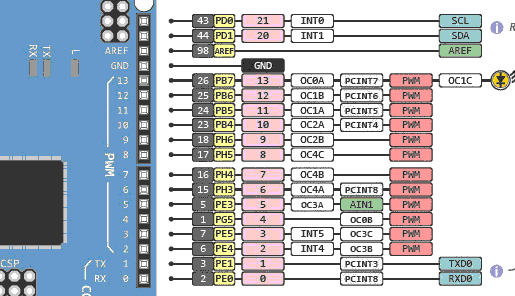
This connector is one of 15 controllable PWM connectors. This is what is indicated on the partial diagram above, where connectors 2 to 13 are marked PWM.
PWM stands for Pulse Width Modulation. This is to send on an output of the ARDUINO card a periodic square signal whose cyclic ratio of controlled duration.
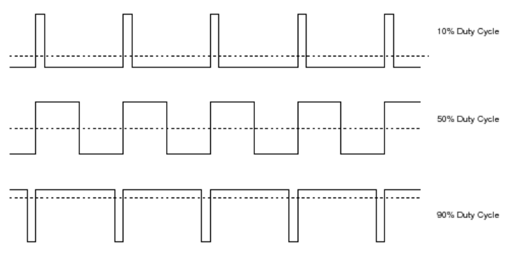
In the figure above, there are three PWM signals, the first with a duty cycle at 10%, the second at 50%, the last at 90%.
PWM duty cycle check
The cyclic report is injected into the OCR1A register pointed to by the
constant of the same name. This is done in the definition of the word led:
\ PWM LED Driver
: led ( n -- )
    OCR1A ! ;
Example of use:
0 led      \ no light
500 led    \ low luminosity
1200 led   \ medium luminosity
3000 led   \ high luminosity
There is a relationship between terminal PB5 and the register OCR1A. Instead of to control our LED in all or nothing via PORTB, we control the report of terminal PB5 via this register OCR1A.
The initialization of the ports becomes:
: init.ports ( ---)
    %00100000 DDRB c!   \ PB5/OC1A set to output
    %10100000 TCCR1A c!
    %00010010 TCCR1B c!
    $4e20 ICR1 !
  ;
Explanations concerning the registers TCCR1A, TCCR1B and ICR1 are covered in another article.