Hacking an rotary encoder
published: 23 October 2019 / updated 31 October 2019

The rotary encoder
We will focus on a rotary encoder. Here is the one we use:
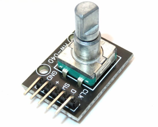
See its technical characteristics
Connection diagram
Here is our connection diagram from the rotary encoder to the ARDUINO MEGA board:
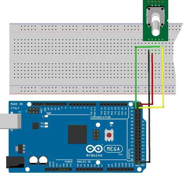
Our rotary encoder has 5 connectors:
| GND | to Arduino GND |
| + | to +5 V Arduino |
| SW | -- not used -- |
| DT | to connector 22 - pin 78 / PA0 |
| CLK | >to connector 23 - pin 77 / PA1 |
These are the port numbers PA0 and PA1 that we will keep in the program in FORTH language.
Caution: do not confuse physical connector numbers and pin numbers
On the ARDUINO cards, the physical connectors are marked, some by numbers, others by their function, example: GND, TX, RX, 5V, etc ...
The mapping for associating pin numbers with physical connectors is in this document:
Pin out map on ARDUINO DUE
Pin out map on ARDUINO MEGA 2560
Pin out map on ARDUINO MICRO
Pin out map on ARDUINO NANO
Pin out map on ARDUINO UNO
Pin out map on ARDUINO YUN
For example, the led '13' which is connected to the ARDUINO MEGA board with the physical terminal 13 is related to the PIN 26. In all our texts, the term "pin" will always refer to PIN code XX as referenced in the technical documents of ARDUINO cards. The mention of a physical connector will be done with the term 'terminal'. Example:
PIN 19 (terminal 53) (penultimate terminal, all at the bottom, left on an ARDUINO MEGA 2560 board)
To learn more about how to program the connectors of the different ARDUINO boards:
Understanding ARDUINO card connectors
Decoding signals from the encoder
Definition of ports and pins used:
34 constant PORTA	\ Port A Data Register
33 constant DDRA	\ Port A Data Direction Register
32 constant PINA	\ Port A Input Pins

%00000001 constant pin78 \ pin 78 connector 22 PA0
%00000010 constant pin77 \ pin 77 connector 23 PA1

: init-ddra-input ( mask ---)
    DDRA mclr    \ init PORT A to input for PA0 and PA1
  ;
Rather than defining globally all the ports and pines, in FORTH, one is satisfied to define the only ports and pines actually used. This strategy avoids proliferation definitions, most of which are not used as is the case in other languages of programming.
The word init-ddra-input accepts a bit mask as input.
Example: pin77 pin78 or init-ddra-input. This activates pins 77 and 78
corresponding to bits 0 and 1 of the PORT A.
Management of the pins used:
: pin@ ( pin PINx --- fl)
    c@   swap and
    if    true
    else  false  then ;

: PA0@ ( --- fl)
    pin78 PINA pin@ ;

: PA1@ ( --- c)
    pin77 PINA pin@ ;
The word pin @ is applicable to any registry bit. He accepts two settings:
- pin which is the pin mask associated with the port to read;
- PORTx which is the address of the data entry port.
Example: pin78 PORTA pin @.
This word pin@ is used in the definitions of PA0@ words and
PA1@.
These PA0@ and PA1@ words directly return a Boolean flag.
This solution facilitates subsequent treatments.
Signal analysis
Here are the signals emitted by our rotary encoder:
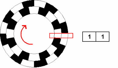
Sequence of signals clockwise (CW) and counterclockwise (CCW):
| CW | | CCW |
|---|---|
| 1 1 | | 1 1 |
| 1 0 | | 0 1 |
| 0 0 | | 0 0 |
| 0 1 | | 1 0 |
| 1 1 | | 1 1 |
Depending on the meaning, there are two interesting sequential sequences:
- clockwise: 11 -> 10, only the least significant bit changes;
- clockwise: 00 -> 01, only the least significant bit changes;
- anticlockwise: 11 -> 01, only the most significant bit changes;
- anti-clockwise: 00 -> 10, only the most significant bit changes;
These are the sequences we will manage:
variable oldPA0
variable oldPA1

variable counter

: getRotation ( PA0 PA1 --- direction )
    over oldPA1 @ <>  over oldPA0 @ =  and
    if
        -1 counter +!
    then
    over oldPA1 @ =   over oldPA0 @ <> and
    if
         1 counter +!
    then
    oldPA1 !   oldPA0 !
  ;
We define two variables oldPA0 and oldPA1 loaded with
remember the previous state of PA0 and PA1.
The counter variable is incremented or decremented based
the result of the execution getRotation.
Ports and variables are initialized:
: inits ( ---)
    pin78 pin77 or  init-ddra-input
    PA0@ oldPA0 !
    PA1@ oldPA1 !
  ;
This part inits must be adapted according to the wiring specific to your ARDUINO card.
: changedPA01? ( PA0 PA1 --- fl)
    oldPA1 @ <> swap oldPA0 @ <> or
  ;
The word changedPA01? returns a boolean flag TRUE if the state of the
data PA0 and PA1 are no longer equal to those stored in
oldPA0 and oldPA1 variables.
And finally, our last definition getR:
: getR ( ---)
    inits
    begin
        PA0@ PA1@
        2dup changedPA01?
        if
            getRotation
            counter @ . cr \ for tracing
        else
            2drop
        then
    key? until ;
The word getR initializes the ports and variables via inits .
Then a begin .. until loop retrieves the values of PA0 and PAI.
If their values have changed, we run getRotation, a word that
increments or decrements the contents of the counter variable.
Here is what gives the execution of the word getR:
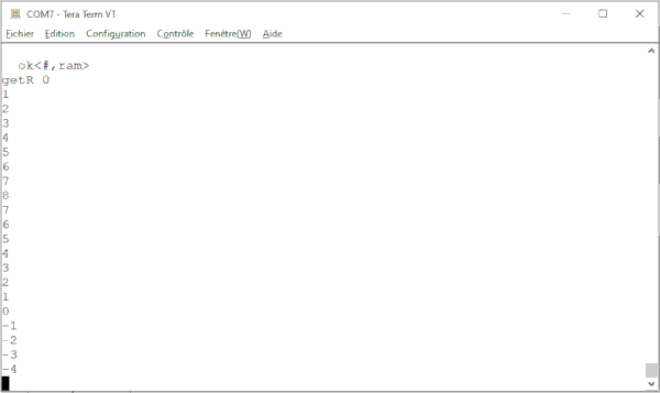
In final operation, the code part counter @. cr could be
deleted or commented out.
The complete listing is available by clicking here.
Redefinition of words PA0@ and PA1@
We can delete the word pin @ and replace it with the word pin:
: pin: ( compil: pin PINX ---  | exec: --- fl)
    create
        , ,
    does>
        dup @ swap 2+ @ swap
        c@   swap and
        if    true
        else  false  then
  ;
The code part after create compiles the pin and PINx values.
The code part after does> retrieves the pin and PINx values and performs
the treatment on these values.
Using the word pin: to setPAO@ and PA1@:
pin78 PINA pin: PA0@
pin77 PINA pin: PA1@