Management of a 4 relay module
published: 14 November 2019 / updated 4 June 2020

The 4 relay module
Find all the explanations on the 4 relay module here:
Module 4 relays
4 relay module wiring
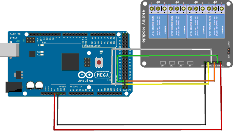
Caution: do not confuse physical connector numbers and pin numbers
On the ARDUINO cards, the physical connectors are marked, some by numbers, others by their function, example: GND, TX, RX, 5V, etc ...
The mapping for associating pin numbers with physical connectors is in this document:
Pin out map on ARDUINO DUE
Pin out map on ARDUINO MEGA 2560
Pin out map on ARDUINO MICRO
Pin out map on ARDUINO NANO
Pin out map on ARDUINO UNO
Pin out map on ARDUINO YUN
For example, the led '13' which is connected to the ARDUINO MEGA board with the physical terminal 13 is related to the PIN 26. In all our texts, the term "pin" will always refer to PIN code XX as referenced in the technical documents of ARDUINO cards. The mention of a physical connector will be done with the term 'terminal'. Example:
PIN 19 (terminal 53) (penultimate terminal, all at the bottom, left on an ARDUINO MEGA 2560 board)
To learn more about how to program the connectors of the different ARDUINO boards:
Understanding ARDUINO card connectors
Our wiring uses the first 4 least significant bits of PORT B.
Definition and initialization of relays
We first define the PORTB as a constant:
\ PORTB
37 constant PORTB	\ Port B Data Register
\ 36 constant DDRB	\ Port B Data Direction Register
\ 35 constant PINB	\ Port B Input Pins - unused
The words defPIN: high low output input and pin@ are described
in the article Definition and management of PORT connections
The word defPIN: then allows to define our relays RELAY1
at RELAY4:
\ definition RELAYx
eeprom
PORTB %00000001 defPIN: RELAY1
PORTB %00000010 defPIN: RELAY2
PORTB %00000100 defPIN: RELAY3
PORTB %00001000 defPIN: RELAY4
ram
Then we create the word init.RELAYS that initializes the
PORT B and relays at rest (NO terminals of the relays in the inactive state):
: init.RELAYS ( ---)
    RELAY1  output
    RELAY2  output
    RELAY3  output
    RELAY4  output
  ;
In the definition of the word init.RELAYS, we retrieve
each value delivered by the execution of the words RELAYx,
we throw the address of PORTB and we make the sum of each mask, here
1 + 2 + 4 + 8 = 15. The DDRB mset sequence selects the four bits
low weight of the PORTB as digital outputs. We previously duplicated
this masking value, which makes it possible to execute the sequence PORTB mset0
which puts these 4 bits in the high state. The 4 relay board thus receives 4 bits in the high state on
terminals IN1 to IN4, causing the relays to rest.
Relay management
Here is the sequence to test the proper functioning of a relay, here relay 1:
init.RELAYS
RELAY1 high
500 ms
RELAY1 low
Practical case: lighting a lamp
The goal is to turn on and off a lamp. The most powerful LED lamps doing in the 25 to 30 Watts, in 220 Volts, it represents a ridiculous amperage that our relays can perfectly manage.
Simple management of a lamp
Connection diagram of a 220V 10W (~ 0.05A) LED lamp:
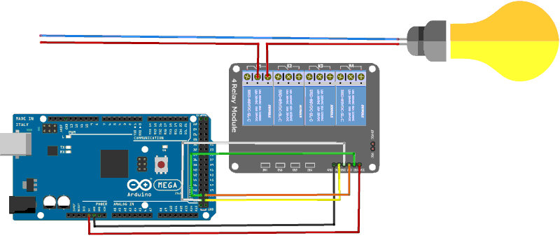
Our lamp being connected to relay 1, we can define:
: led.lamp.ON ( ---)
    RELAY1 high         \ turn lamp ON
  ;
: led.lamp.OFF ( ---)
    RELAY1 low        \ turn lamp OFF
  ;
It is very easy to test these words from the terminal in interpreted mode.
simply typing led.lamp.ON to turn on the lamp,
led.lamp.OFF to turn off the lamp.
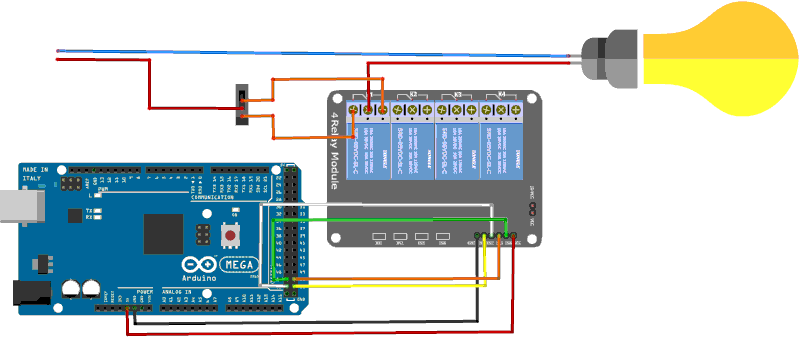
Management of a lamp back and forth
The goal is to double the control of a lamp, ceiling style. This lamp is activated by a conventional wall switch from a single point. For our relay can turn on the lamp in double order, it is necessary:
- disassemble the single wall switch;
- replace this switch with a switch type back and forth.
Mounting with relay 1:
-- ATTENTION ---
The connection wires of the lamp being under 220V, always work out voltage, ie by cutting the power supply upstream.
Once this assembly is done, the lamp can be ordered from the ARDUINO board or from the switch. Truth table:
| Inter. | RELAY | LAMP |
|---|---|---|
| OFF | OFF | ON |
| OFF | ON | OFF |
| ON | OFF | ON |
| ON | ON | OFF |
To complete the programming of this lamp, we need another word who will perform the control relay rocker:
: led.lamp.TOGGLE ( ---)
    RELAY1 pin@               \ get relay state
    if
        led.lamp.OFF        \ turn lamp OFF
    else
        led.lamp.ON         \ turn lamp ON
    then
  ;
The remote command will only have to execute the word led.lamp.TOGGLE
for the lamp to change state.
It is obvious that said remote command is a command executed near the lamp to be controlled, for example using an infra-red remote control.
Note that at each stage of programming, we capitalize the definitions previously created:
- creating short definitions, so easy to develop;
- a contextual naming, making the words explicit, example
led.lamp.TOGGLE;
The entire relay and lamp management program occupies less than 400 bytes in
eeprom memory. Each definition can be executed in interpreted mode via the terminal. See:
Communicate with Flash Forth:
To compile a program in FORTH language, simply connect via a USB port on the map ARDUINO and copy/paste the portions of FORTH code into the terminal. We can launch a terminal from any system: Windows, Linux, MacOS, etc ...
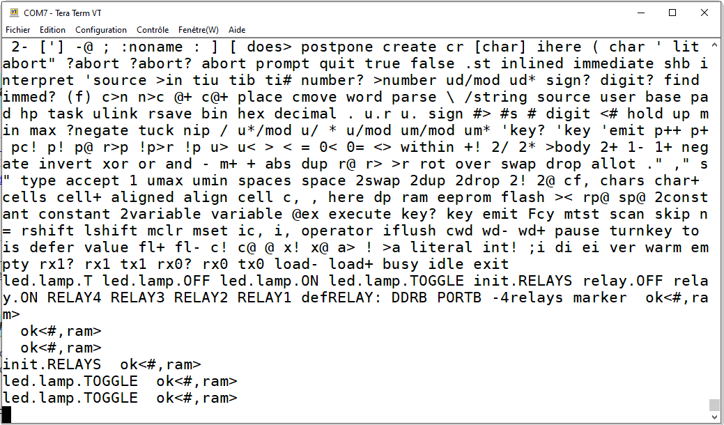
Once the definitions are compiled, we can execute them from the terminal, as we see on the screen copy above.
You can turn off the ARDUINO board with previously compiled definitions.
When you turn on the ARDUINO card again, you will find all previously compiled words.
Just type words to find these compiled words (see screenshot above).
The complete listing is available here: Management of a 4 relay module