Sleep mode on ARDUINO cards
published: 22 December 2020 / updated 22 December 2020
SLEEP mode
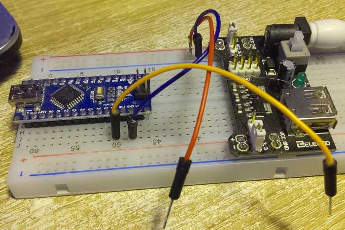
ARDUINO cards incorporate a micro-controller. This micro-controller, when it works normally consumes some current. Here is the assembly made to measure consumption an ARDUINO NANO card:

The ARDUINO NANO card is powered in two ways:
- via the USB / serial port (on the left in the photo above)
- by inputs (27) +5V and (29) GND on the diagram below:

On the photo, we derive the power supply +5V towards a milliAmperemeter.
The +5V power supply is taken from a power supply stabilized (on the right in the photo above).
We activate this power supply, then we connect the milliAmperemeter. The ARDUINO NANO card lights up and the milliAmperemeter display shows 18.3 mA.
Activating IDLE
The idle sleep mode is the only mode available with FlashForth. Here is a very simple definition
to use this mode:
: myBoot ( ---)
    ei  idle ;
This definition can only be entered with the ARDUINO NANO card connected to the USB port of the PC and via the terminal.
If you run myBoot, nothing seems to happen. However, the ARDUINO card is
switched to sleep mode.
In order to measure the correct execution of idle which is in the definition of myBoot, it
must tell FlashForth to run myBoot at startup:
' myBoot is turnkey
We unplug the USB port. Turn the stabilized power back on, then prepare for perform a new current measurement with our milliAmeter.
As soon as the milliAmpeter is connected, the ARDUINO NANO card turns on, the current measurement reads 18.3 mA for about a second, then changes to 11.8 mA!
The LED which indicates that our ARDUINO NANO card has been switched on correctly remains on.
The ARDUINO NANO card will exit IDLE mode as soon as it is requested by:
- a transmission via the serial port (2) D0/RX;
- a hardware interrupt via a port that accepts this type of interrupt;
- an internal timer type interrupt for example...
The IDLE sleep mode in C language:
LowPower.idle(SLEEP_8S, ADC_OFF, TIMER2_OFF, TIMER1_OFF, TIMER0_OFF, SPI_OFF, USART0_OFF, TWI_OFF);
The different sleep modes
As we have seen, the sleep mode idle brings back the current consumption
from 18.3 mA to 11.8 mA, i.e. 6.5 mA, i.e. a gain in consumption of
30%. We can do better, but that's not the subject of our article.
The different sleep modes are controlled by the SMCR register (Sleep Mode Control Register) whose structure is as follows:
| 7 | 6 | 5 | 4 | 3 | 2 | 1 | 0 |
|---|---|---|---|---|---|---|---|
| ----- | ----- | ----- | ----- | SM2 | SM1 | SM0 | SE |
Bit b0, marked SE (Sleep Enable) authorizes sleep mode if its content is 1.
The other bits SM0, SM1 and SM2 are used to select a sleep mode:
| SM2 | SM1 | SM0 | Sleep Mode |
|---|---|---|---|
| 0 | 0 | 0 | Idle |
| 0 | 0 | 1 | ADC Noise Reduction |
| 0 | 1 | 0 | Power-down |
| 0 | 1 | 1 | Power-save |
| 1 | 0 | 0 | Reserved |
| 1 | 0 | 1 | Reserved |
| 1 | 1 | 0 | Standby |
| 1 | 1 | 1 | External Standby |
Note: 1. Standby mode is only recommended for use with external crystals or resonators.
On the ATmega328P, Idle mode is the only sleep that leaves interrupts enabled AND the USART running. This means you can wake up out of IDLE mode just by sending a char to the USART.
For all other sleep modes, you must either use reset or provide some kind of timed or external event to wake up the USART won't work.
For those who would like to drastically reduce the current consumption of their ARDUINO card NANO, here is a video that explains some manipulations:
Attention: in the video, you can remove the current regulator. If you do, you will be forced to supply your ARDUINO NANO card with a current source having a voltage strictly between 3.5 and 5.5 Volts!
Marc PETREMANN
